Prosthetic ankle and foot combination

a technology of prosthesis and ankle, applied in the field of prosthetic ankle and foot combination, can solve the problems of affecting affecting the efficiency of the device, and maintaining forward motion, so as to reduce the flexion moment about the knee, reduce the resistance to plantarflexion, and improve the stability of the devi

Active Publication Date: 2011-07-26
BLATCHFORD PRODS
View PDF21 Cites 111 Cited by
  • Summary
  • Abstract
  • Description
  • Claims
  • Application Information

AI Technical Summary

Benefits of technology

[0011]Advantageously, the control system is programmed to generate signal indicative of terrain, e.g. ground inclination, and to vary the degree of damping resistance in the direction of both ankle dorsiflexion and ankle plantarflexion. Particular benefits are achieved if the damping resistance in the direction of plantarflexion is automatically decreased when the control system generates signals indicative of walking down an incline and increased when indicative of walking up an incline, compared with a level of resistance in that direction set for walking on the level. Conversely, it is preferable that the control system operates such that the damping resistance in the direction of dorsiflexion is increased compared with the level walking resistance level in the dorsiflexion direction when the control system signals are indicative of walking down an incline and decreased when the signals are indicative of walking up an incline.
[0048]According to yet a further variant, a lower limb prosthesis comprises a shin component, a foot component, a joint mechanism interconnecting the foot and shin components and arranged to allow limited damped pivoting of the foot component relative to the shin component about a medial-lateral flexion axis during locomotion, and a control system having at least one sensor for generating signals indicative of at least one characteristic of locomotion, the joint mechanism including a device for adjusting, the limit of dorsiflexion of the foot component relative to the shin component during locomotion. Typically the control system is arranged to generate signals indicative of walking on stairs or on an incline and to alter the dorsiflexion limit to increase the maximum degree of dorsiflexion permitted by the joint mechanism when such signals are produced compared with the degree of dorsiflexion permitted by the adjusting device when signals are generated indicative of walking on level ground. A further adjusting device may be included for adjusting the degree of damping resistance of the joint mechanism in the directions of dorsiflexion and plantarflexion respectively in response to signals from the control system, the control system and the joint mechanism being arranged such that the dorsiflexion limit and the damping resistances are independently adjustable during locomotion.

Problems solved by technology

However, such a device is often uncomfortable for the user whilst standing and walking on ramps and stairs and walking at different speeds.
Users have also experienced knee instability and difficulty in maintaining forward motion during roll-over of the foot while standing and walking on ramps and stairs, with consequent impairment of efficiency.
These difficulties are particularly important for transfemoral amputees whose stance phase action is normally compromised by significantly reduced knee flexion and extension which would otherwise assist shock absorption and forwards propulsion during the stance phase.
Another aspect of ankle-foot function and transfemoral amputee locomotion relates to the way in which a typical known prosthesis hinders the amputee, resulting in poor body posture for certain locomotion activities such as ascending and descending stairs and ramps, which diminishes the potential for application of voluntary control, particularly user-generated hip extension torque.
The poor posture described is largely caused by inappropriate stiffness and range of motion at the ankle which does not allow the body centre of mass to pass easily over the ankle.

Method used


Image

  • Prosthetic ankle and foot combination
  • Prosthetic ankle and foot combination
  • Prosthetic ankle and foot combination

Examples


Embodiment Construction

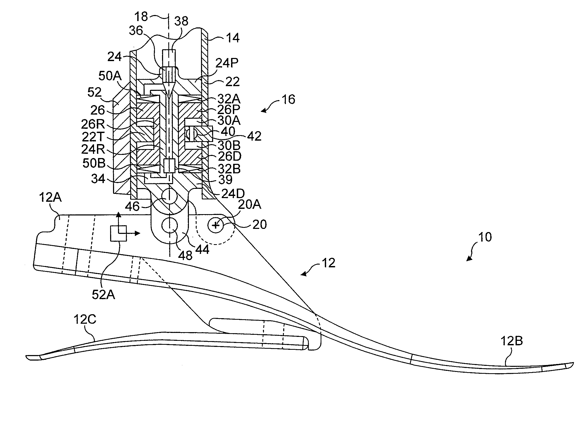
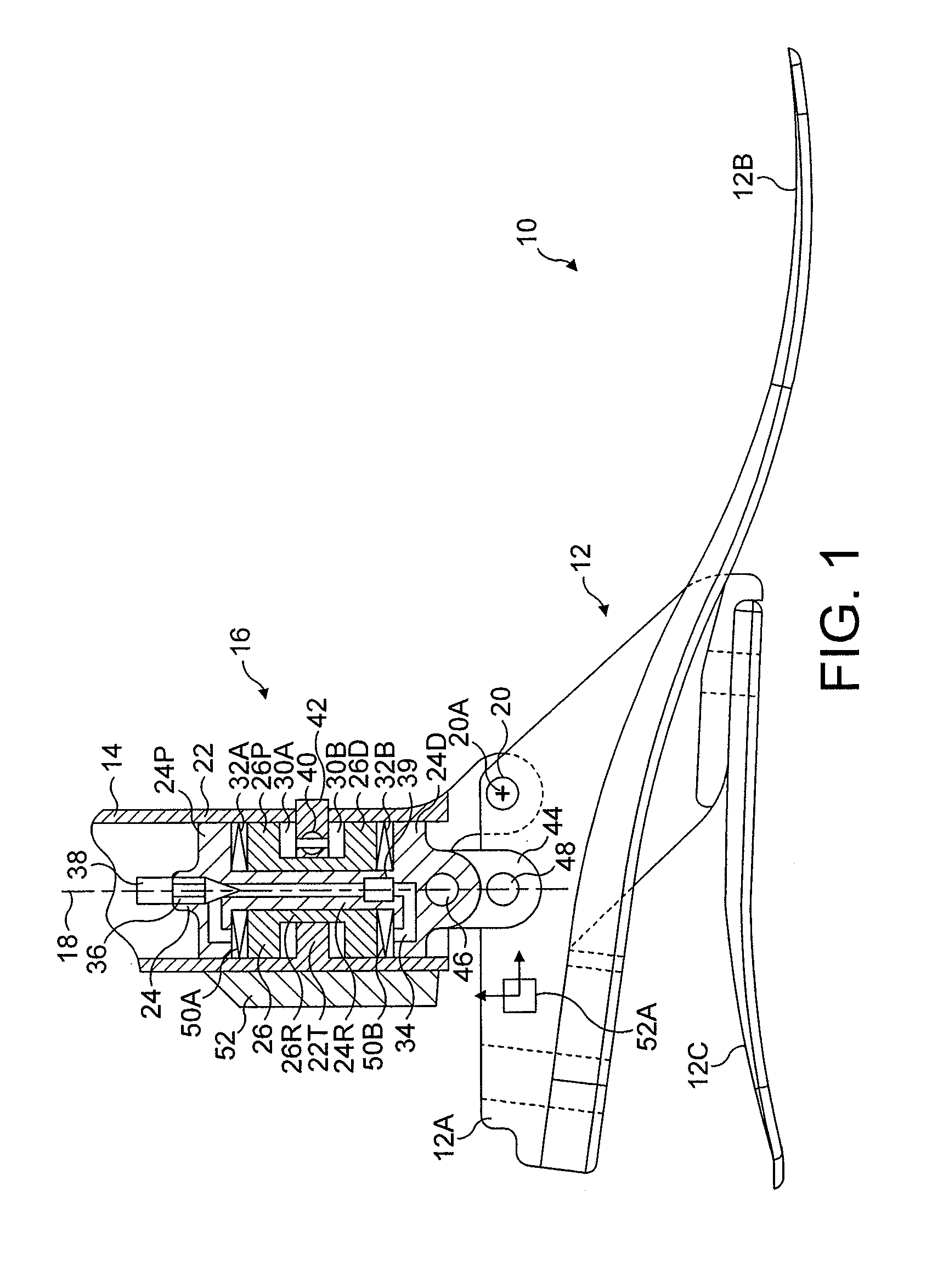
[0066]Referring to FIG. 1, a lower limb prosthesis in accordance with the invention has a foot component 10 with a foot keel 12 comprising a rigid carrier 12A. Independently coupled to the rigid carrier 12A are a toe spring 12B and a heel spring 12C. The keel 12 is largely formed from carbon fibre composite material and can be surrounded by a foam cosmetic covering (not shown).

[0067]Coupled to the foot keel 12 is a shin component 14 having, at its distal end, an ankle joint mechanism 16 which is housed largely within the shin component 14 and connects the shin component 14 to the foot keel 12. The shin component 14 defines a shin axis 18. The mounting of the shin component 14 to the foot keel 12 is by way of an ankle flexion pivot 20 defining a flexion axis 20A running in a medial-lateral direction to the anterior of the shin axis 18. The ankle joint mechanism is in the form of a piston and cylinder assembly, the cylinder 22 of which forms an extension of a shin tube centred on the ...


PUM


Abstract

A prosthetic ankle and foot combination has an ankle joint mechanism constructed to allow damped rotational movement of a foot component relative to a shin component. The mechanism provides a continuous hydraulically damped range of ankle motion during walking with dynamically variable damping resistances, and with independent variation of damping resistances in the plantarflexion and dorsiflexion directions. An electronic control system coupled to the ankle joint mechanism includes at least one sensor for generating signals indicative of a kinetic or kinematic parameter of locomotion and / or walking environment, the mechanism and the control system being arranged such that the damping resistances effective over the range of motion of the ankle are adapted automatically in response to such signals. Single and dual piston hydraulic damping arrangements are disclosed, including arrangements allowing independent heel-height adjustment.

Description

CROSS-REFERENCE TO RELATED APPLICATIONS[0001]This is a continuation-in-part of U.S. application Ser. No. 11 / 956,391 filed Dec. 14, 2007 which claims the benefit of Provisional Application No. 60 / 869,959 filed Dec. 14, 2006. The present application claims the benefit of Provisional Application No. 60 / 891,075 filed Feb. 22, 2007. The entire contents of such applications are incorporated by reference in the present application.FIELD OF THE INVENTION[0002]This invention relates to a prosthetic ankle and foot combination arranged to allow damped ankle flexion. The invention also includes a lower limb prosthesis incorporating such an ankle and foot combination.BACKGROUND OF THE INVENTION[0003]Current prosthetic ankle-foot systems are generally aligned for operation as fixed mechanical structures comprising elastic and deformable elements designed to provide stability during standing and walking and to return energy for propulsion into the swing phase of the walking cycle. However, such a ...

Claims


Application Information

Patent Timeline
Patent Type & Authority Patents(United States)
IPC IPC(8): A61F2/66A61F2/72A61F2/64
CPCA61F2/6607A61F2/68A61F2002/5038A61F2002/30359A61F2002/5006A61F2002/5018A61F2002/5033A61F2002/6621A61F2002/6642A61F2002/6657A61F2002/6854A61F2002/704A61F2002/745A61F2002/748A61F2002/7625A61F2002/764A61F2220/0033A61F2002/5036A61F2002/5043A61F2002/74A61F2002/5035A61F2002/6614A61F2002/708A61F2/70A61F2/74A61F2/748
Inventor MOSER, DAVIDABIMOSLEH, FADIZAHEDI, MIR SAEEDHARRIS, GRAHAMLANG, STEPHEN TERRYSYKES, ANDREW JOHN
Owner BLATCHFORD PRODS
Why Eureka
Try Eureka