Indicator and indicator-structure

Active Publication Date: 2009-07-02
BROTHER KOGYO KK
View PDF7 Cites 107 Cited by
  • Summary
  • Abstract
  • Description
  • Claims
  • Application Information

AI Technical Summary

Benefits of technology

[0043]In this arrangement, it is possible to enhance the degree of the change of the deformation of the indicator caused by the applied force, by providing the thin-walled section at the boundary portion between the plate-shaped member of the indicator and the attachment section. It is possible to increase the luminance of the light emission effected by the stress light-emitting material.
[0044]The indicator according to the present invention is provided with, for example, the plate-shaped member in which the stress light-emitting material is applied to the plurality of stress-concentrating sections. When the force is applied to the stress-transmitting section of the indicator, then the applied force is transmitted to the stress-concentrating sections, and the stress light-emitting material, which is applied to one or two or more of the stress-concentrating sections, emits the light in accordance with the magnitude of the force. Therefor

Problems solved by technology

Therefore, it is difficult to visually recognized the magnitude of the force brought about by being pushe

Method used


Image

  • Indicator and indicator-structure
  • Indicator and indicator-structure
  • Indicator and indicator-structure

Examples


first embodiment

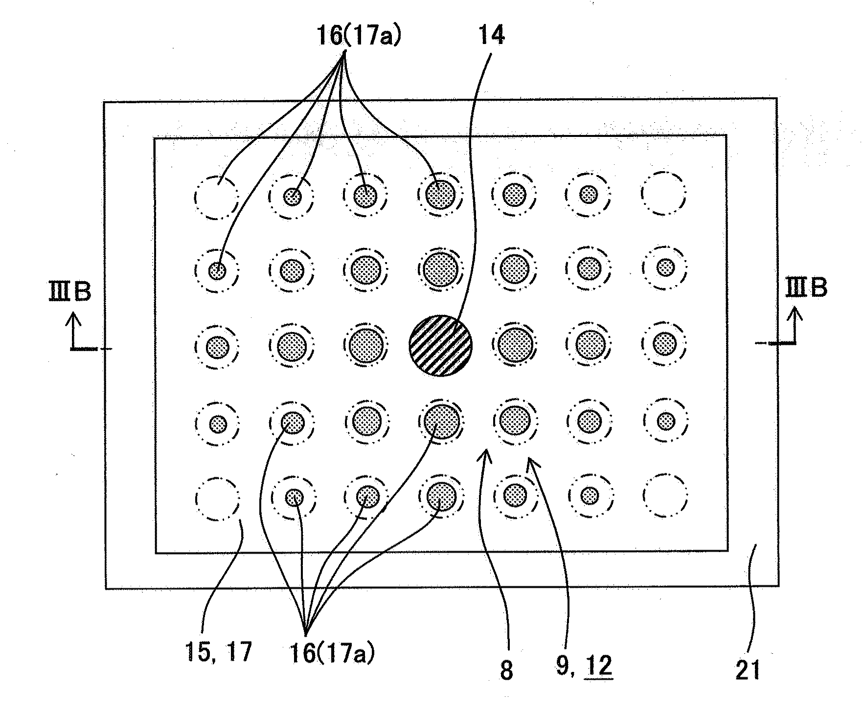
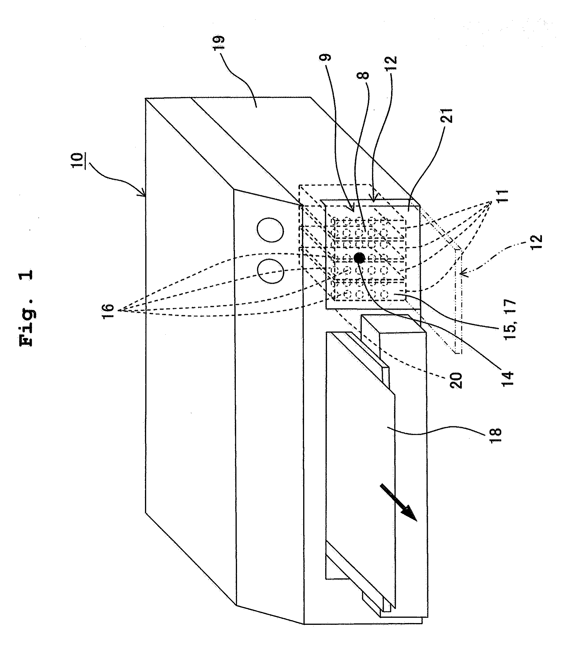
[0059]An explanation will be made with reference to FIGS. 1 to 7 about a first embodiment of an indicator according to the present invention and an indicator-structure provided with the indicator. As shown in FIG. 1, for example, the indicator-structure 9, which is provided with the indicator 8, is applied to a cartridge lid member 12 for covering four ink cartridges (liquid supply sources) 11 installed to a cartridge-installing section of an ink-jet printer 10.

[0060]Respective four color inks (black, cyan, magenta, and yellow) are stored in the four ink cartridges 11 installed on the depth side (back side) of the cartridge lid member 12 shown in FIG. 1 respectively. The inks, which are stored in the respective ink cartridges 11, are supplied to a head unit via unillustrated four ink supply tubes. The inks, which are supplied to the head unit, are discharged from a large number of nozzle holes provided on the lower surface of the head unit. The inks are jetted onto a recording mediu...

second embodiment

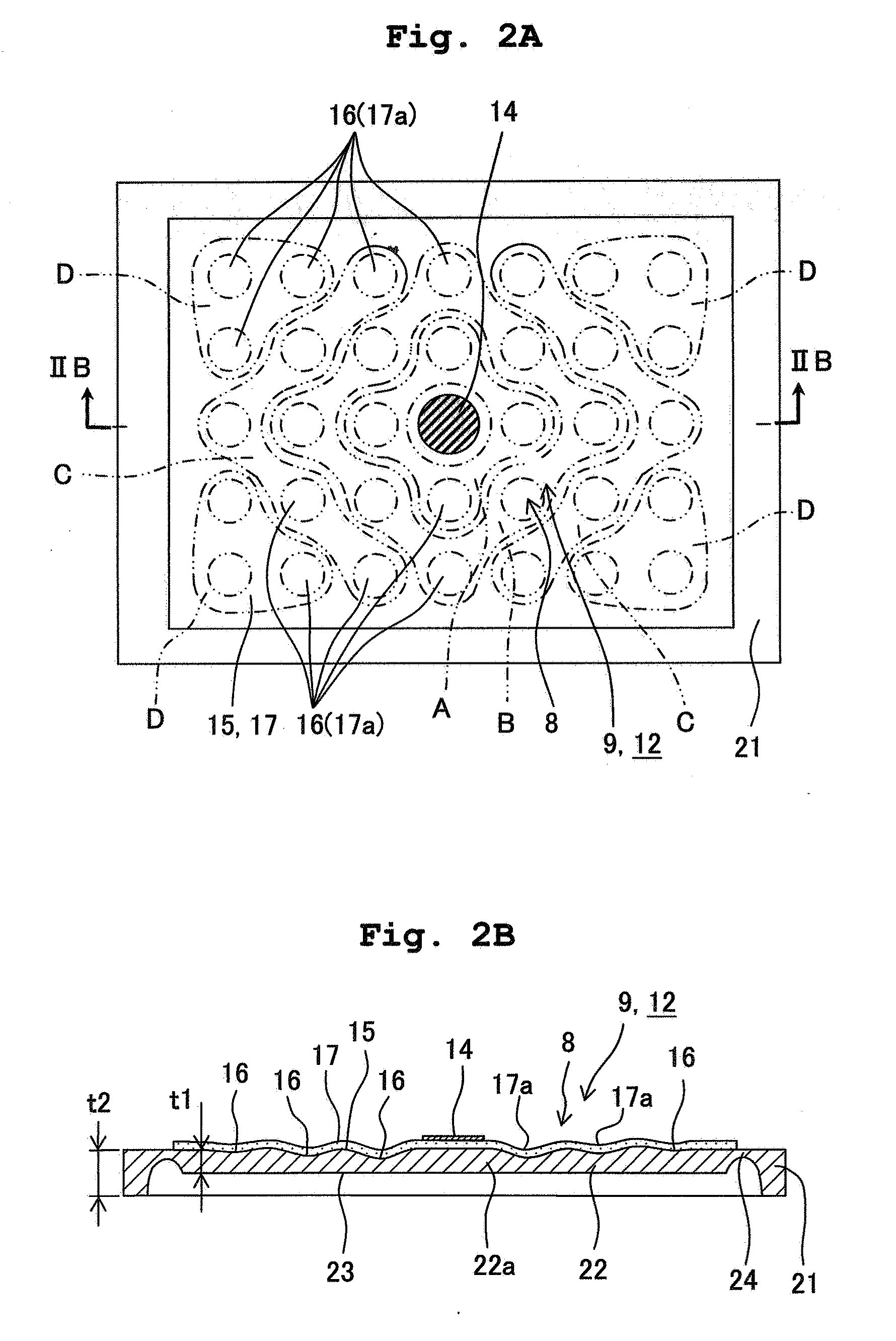
[0098]Next, an explanation will be made with reference to FIG. 8 about a second embodiment of an indicator according to the present invention and an indicator-structure provided with the indicator. The indicator-structure 31 provided with the indicator 8 is also applied to the cartridge lid member 12 of the ink-jet printer 10 in the same manner as in the first embodiment. The second embodiment shown in FIG. 8 is different from the first embodiment shown in FIGS. 2A and 2B as follows. In the case of the first embodiment shown in FIGS. 2A and 2B, the attachment section 21 has the thickness and the rigidity larger than those of the indicator 8, and the rectangular frame-shaped thin-walled section 24 is formed at the boundary portion between the outer circumferential portion of the indicator 8 and the inner circumferential portion of the attachment section 21. On the contrary, in the case of the second embodiment shown in FIG. 8, the attachment section 32 has the thickness and the rigid...

third embodiment

[0102]Next, an explanation will be made with reference to FIGS. 9A and 9B about a third embodiment of an indicator according to the present invention and an indicator-structure provided with the indicator. The indicator-structure 36 provided with the indicator 35 is also applied to the cartridge lid member 12 of the ink-jet printer 10 in the same manner as in the first embodiment.

[0103]The indicator-structure 36 of the third embodiment shown in FIGS. 9A and 9B resides in a rectangular plate-shaped member having a substantially constant thickness. A plurality of stress-concentrating sections 16 are provided on the surface 15 of the plate-shaped member in the same manner as in the first embodiment.

[0104]The plate-shaped member is formed such that a powder of a stress light-emitting material is mixed and dispersed in a synthetic resin material having the light-transmissive property. In other words, the plate-shaped member itself is the stress light-emitting section. In the rectangular ...


PUM


Abstract

An indicator for emitting a light is provided, the indicator comprising a plate-shaped member which has a stress-concentrating section for causing stress concentration, and a stress-transmitting section for transmitting, to the stress-concentrating section, a stress generated due to an external force; wherein the stress-concentrating section is provided with a stress light-emitting section which is formed of a stress light-emitting material that emits the light in response to a change of the stress. The stress-concentrating section can be arranged such that the stress-concentrating section is not hidden by a finger when the force is applied to the indicator with the finger or the like. The visibility of the light emission can be secured by the light emission effected by the stress light-emitting material applied to the stress-concentrating section which is not hidden by the finger.

Description

CROSS REFERENCE TO RELATED APPLICATION[0001]The present application claims priority from Japanese Patent Application No. 2007-341545, filed on Dec. 29, 2007, the disclosures of which are incorporated herein by reference in its entirety.BACKGROUND OF THE INVENTION[0002]1. Field of the Invention[0003]The present invention relates to an indicator and an indicator-structure which are provided, for example, for lids and trays of electric apparatuses, electronic apparatuses, and mechanical apparatuses, wherein the indicator is capable of indicating the magnitude of the force applied to the lid, the tray or the like by means of the light.[0004]2. Description of the Related Art[0005]Conventionally, as shown in FIG. 13, for example, a switch 1 is provided, wherein when a stress light-emitting member film 2, which serves as an operating section of the switch 1, is pushed or pressed with a finger 3, the stress light-emitting member film 2 emits the light in accordance with the pushing force (s...

Claims


Application Information

Patent Timeline
IPC IPC(8): G08B21/00
CPCG01L1/247G06F3/0488
Inventor SUGAHARA, HIROTO
Owner BROTHER KOGYO KK
Why Eureka
Try Eureka