
Catadioptric system, apparatus, and method for producing images on a universal, head-up display

Active Publication Date: 2010-06-08
ROCKWELL COLLINS INC
View PDF5 Cites 94 Cited by
  • Summary
  • Abstract
  • Description
  • Claims
  • Application Information

AI Technical Summary

Benefits of technology

[0012]In another embodiment, a HUD apparatus is comprised of a housing assembly containing a catadioptric optical module and attached to a combiner arm assembly. The module could be configured with an interface for receiving non-polarized beams of light, a beam splitter, and a correcting lens. Also, a the module could be configured with an interface for receiving polarized beams of light, a polarization beam splitter, a quarter-wave retarder, a collimating mirror, and a correcting lens. A combiner arm assembly could be configured for receiving collimated beams of light comprising one or more combiners, where the use of multiple combiners allows the instantaneous field of view of the viewer to expand. In an additional embodiment, the combiner arm assembly could be pivotally attached to the housing assembly.
[0013]In another embodiment, a method for producing an image in a catadioptric HUD system is comprised of receiving beams of light, subjecting the beams to a beam splitter, altering beams subjected to the beam splitter, subjecting the altered beams to the beam splitter, collimating the altered beams subject to the beam splitter, and subjecting the collimated beams to at least one combiner, where the use of multiple combiners may expand the instantaneous field of view. In one embodiment, a collimating mirror alters the beams. In another embodiment, subjecting the beams to a quarter-wave retarder, a collimating mirror, and the quarter-wave retarder again alter the beams.

Problems solved by technology

Lens designs that achieve the necessary optical performance tend to be complex and expensive, especially when the field of view (“FOV”) is high and the diameter of the lens is large.
Generally, the size, weight, and complexity of these optical systems detrimentally affect the costs for an operator to employ them.
If such system were to attempt to employ a corrective lens, such lens would cause a significant distortion of the real world scene because it would have to be placed between viewer and the combining surface of the block.
Also, these are large and bulky conventional optics which are heavy and utilize considerable installation space.

Method used


Image

  • Catadioptric system, apparatus, and method for producing images on a universal, head-up display
  • Catadioptric system, apparatus, and method for producing images on a universal, head-up display
  • Catadioptric system, apparatus, and method for producing images on a universal, head-up display

Examples


Embodiment Construction

[0023]In the following description, several specific details are presented to provide a thorough understanding of embodiments of the invention. One skilled in the relevant art will recognize, however, that the invention can be practiced without one or more of the specific details, or in combination with other components, etc. In other instances, well-known implementations or operations are not shown or described in detail to avoid obscuring aspects of various embodiments of the invention.

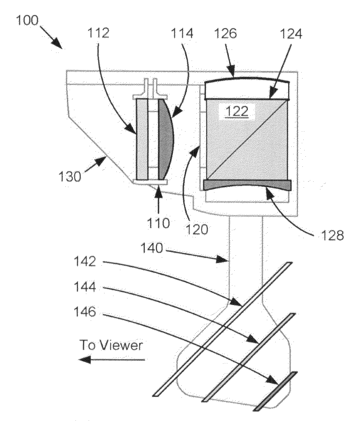
[0024]FIGS. 3A and 3B depict catadioptric head-up display (“HUD”) apparatuses 100 and 100′ suitable for implementation of the techniques described herein. Each respective apparatus may be comprised of an image source module 110 and 110′, a catadioptric optical module 120 and 120′, and a combiner arm 140 and 140′. For the purposes of discussion herein, the components of catadioptric HUD apparatus 100 as embodied in FIG. 3A may be considered the same as those of catadioptric HUD apparatus 100′ as embo...


PUM


Abstract

A present novel and non-trivial system, apparatus, and method for employing a catadioptric optical system in a Head-Up Display (“HUD”) system are disclosed. A catadioptric optical module is configured to produce a large image size within a small space envelope by folding the optical path back through module and separating the paths by use of a beam splitter. Such module comprised of a beam splitter, collimating mirror, and correcting lens produces collimated beams of light from an image source providing either polarized or non-polarized beams of light. If polarized beams are provided, the module includes a quarter-wave retarder, and the configuration of the module permits the image source to provide either s-polarized or p-polarized beams. A combiner arm assembly comprising of at least one combiner receives the collimated beams, where the employment of a plurality of combiners extends the relatively small instantaneous field of view.

Description

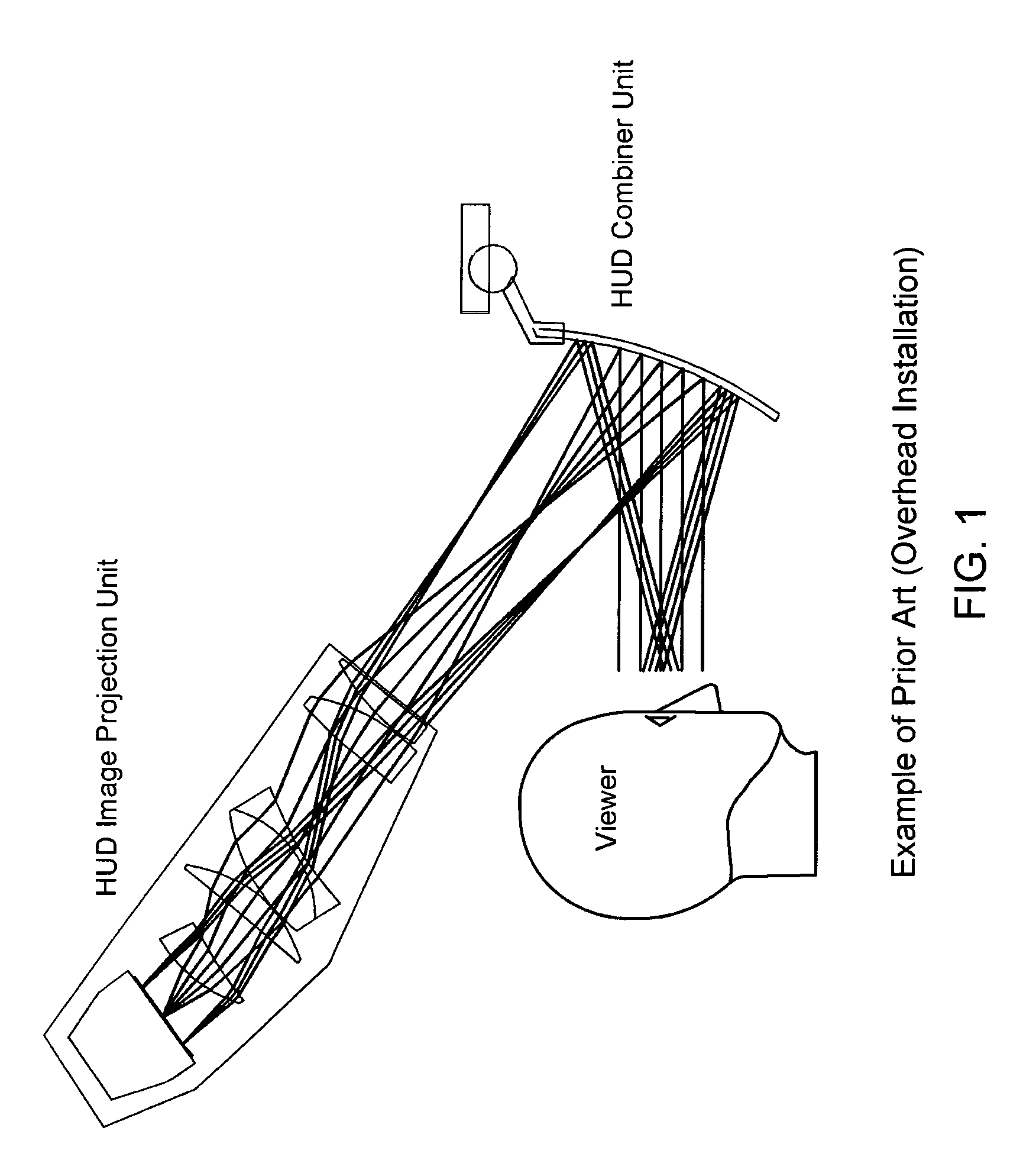
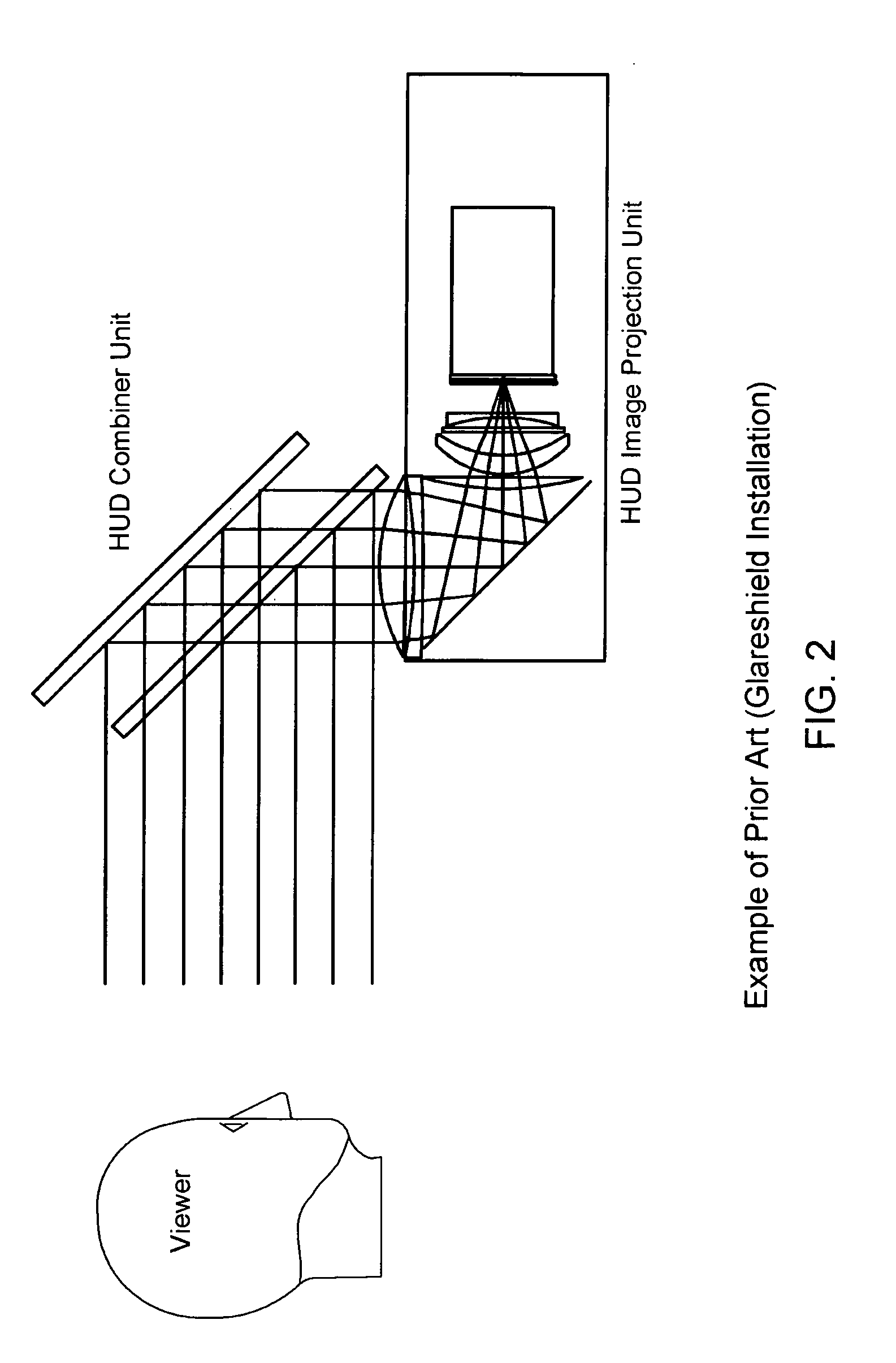
BACKGROUND OF THE INVENTION[0001]1. Field of the Invention[0002]This invention pertains to the field of Head-Up Displays (“HUDs”) that provide images in the field of view of a person viewing the scene outside of a vehicle such as an aircraft or automobile.[0003]2. Description of the Related Art[0004]A HUD is typically any transparent display that presents an image without obstructing the viewer's view or requiring the viewer to look away from the scene outside of a vehicle such as an aircraft or automobile while flying or driving. Initially developed for use in military aircraft, HUDs are used in commercial and private aircraft, automobiles, and other applications. HUD systems may be comprised of a plurality of components including, but not limited to, an image projection unit and a partially transparent and reflective optic commonly referred to as a combiner.[0005]In general, a HUD uses a combination of lenses to create a collimated image. Lens designs that achieve the necessary op...

Claims


Application Information

Patent Timeline
IPC IPC(8): G02B27/14
CPCG02B17/0856G02B27/0101G02B27/148G02B27/283G02B5/30G02B2027/0123G02B2027/011G02B2027/0116G02B2027/0118
Inventor BROWN, ROBERT D.STAHL, KURT A.QUAST, GERHARDT A.WOOD, ROBERT B.JOPES, KEVIN E.
Owner ROCKWELL COLLINS INC
Learn More