Height adjustment mechanism for armrest

a technology of height adjustment and armrest, which is applied in the direction of chairs, vehicle components, vehicle arrangements, etc., can solve the problems of inconvenient use and more effort for users, and achieve the effect of simplifying the height adjustment mechanism of the armrest and enhancing the convenience of us

Inactive Publication Date: 2010-06-29
ISOTECH PRODS
View PDF10 Cites 58 Cited by
  • Summary
  • Abstract
  • Description
  • Claims
  • Application Information

AI Technical Summary

Benefits of technology

[0003]Therefore it is a primary object of the present invention to provide an armrest adjustment mechanism. The armrest adjustment mechanism includes a sleeve, a tubular member, a slider, a long plate, a fixing plate, a guiding plate, a retaining block, a lower base, an armrest pad and a lever arm. The armrest adjustment mechanism features on that: an insertion hole is disposed on upper end of the long plate while the lever arm is arranged between the armrest pad and the lower base. The lever arm inserts through the insertion hole on top end of the long plate so that the long plate hangs on the lever arm, working as the load. One end of the lever arm is arranged on one side of the lower base, working as the fulcrum while the other end of the lever arm is arranged on an opposite side of the lower base correspondingly. A push member projecting from a corresponding opening of the lower base is arranged on the other end of the lever arm, working as the effort. Thus the push member is moved upwards by being pushed by the user from the outside or elastically turned back to the original position so as to work like a Type-2 lever. By pushing the push member to move upwards, the lever arm is driven to make the long plate move upwards synchronously. Therefore, the adjustment of the armrest height is achieved by manual operation of the long plate. Moreover, the height adjustment mechanism of the armrest is simplified and convenience of use is enhanced.

Problems solved by technology

However, the pulling-up of the handle 41 mentioned above requires more effort and is inconvenient for the user.

Method used


Image

  • Height adjustment mechanism for armrest
  • Height adjustment mechanism for armrest
  • Height adjustment mechanism for armrest

Examples


Embodiment Construction

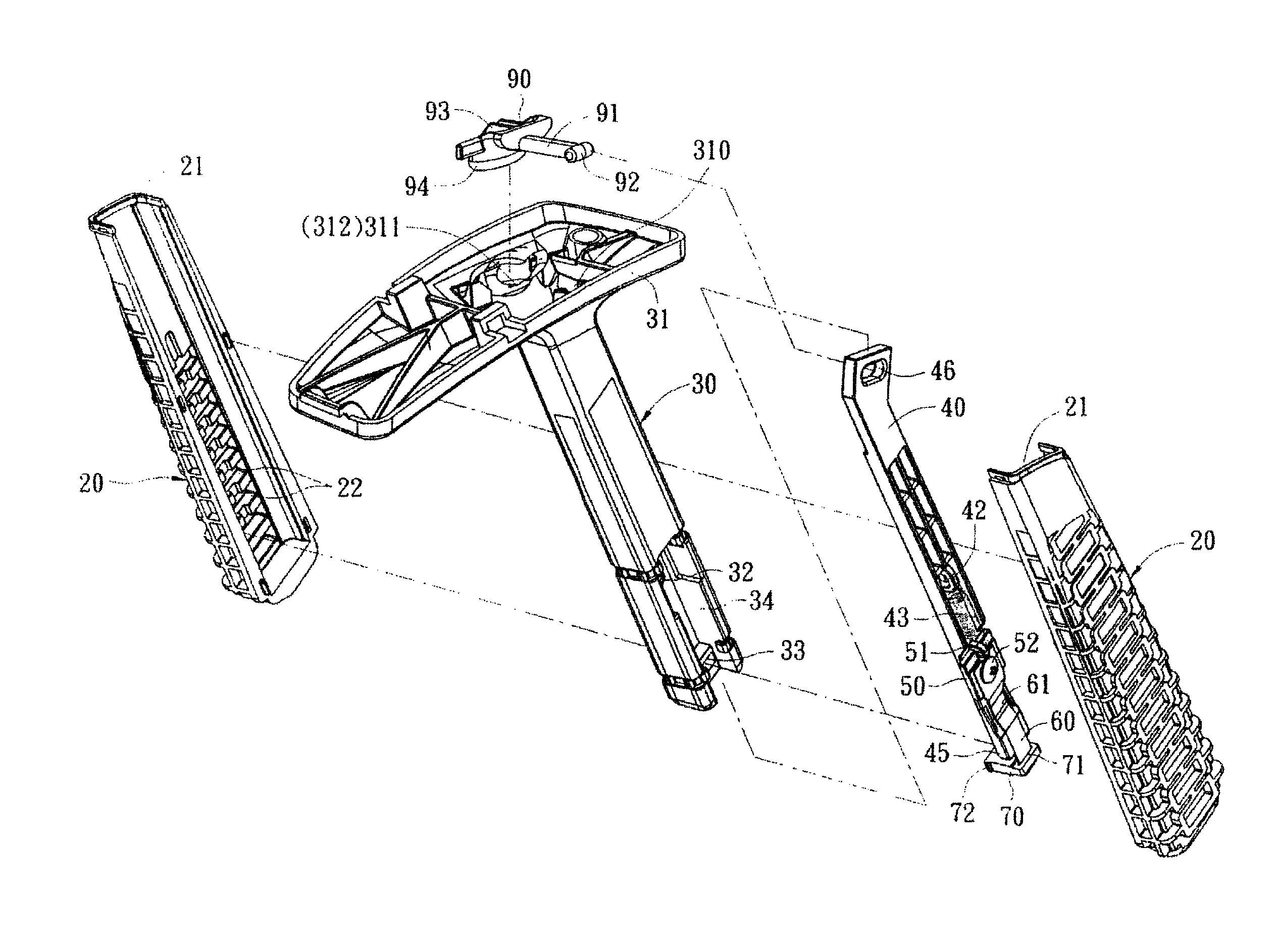
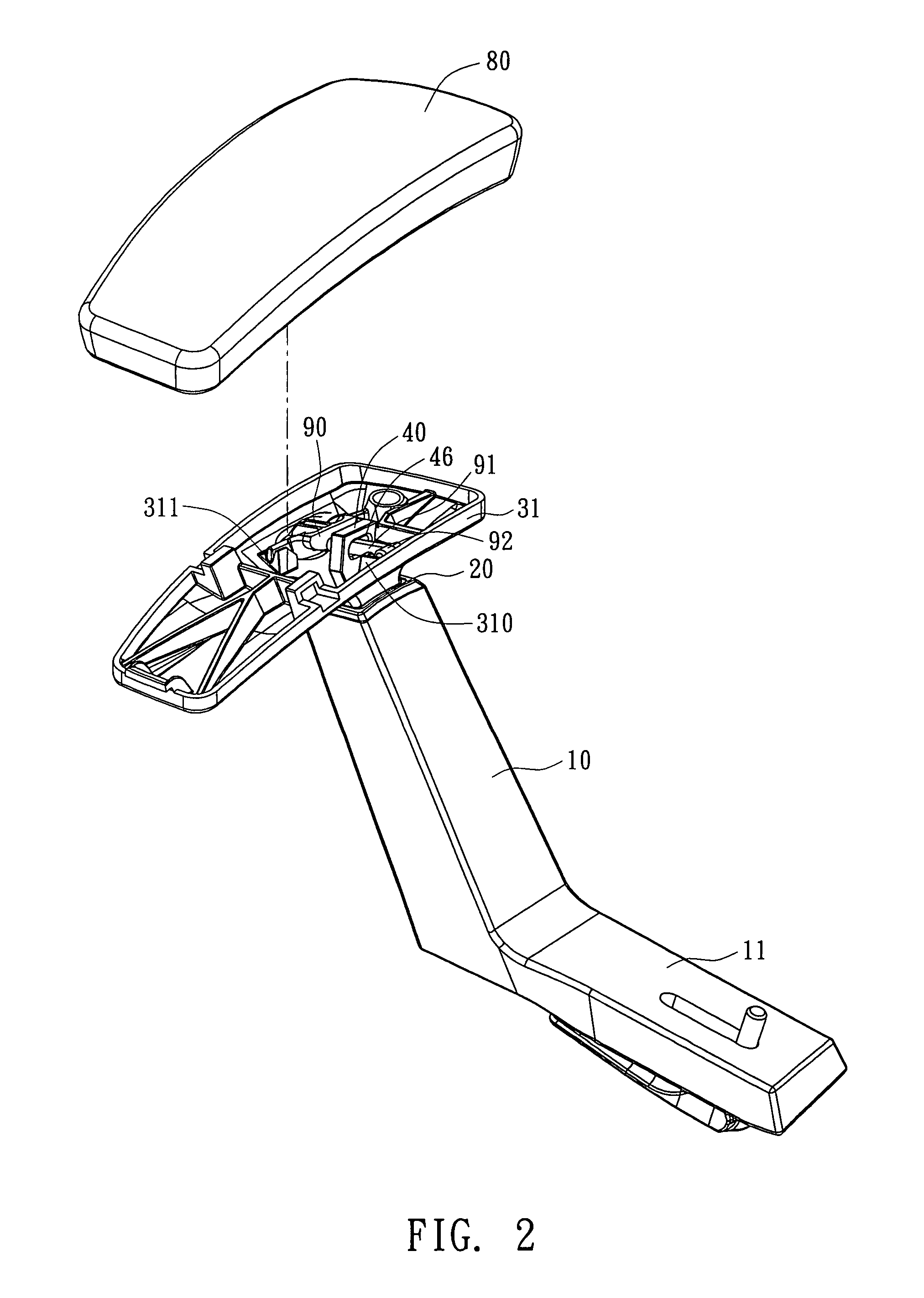
[0015]The present invention is based on the prior art (U.S. Pat. No. 6,336,680) mentioned above-mentioned. The present invention includes a sleeve 10, a tubular member 20, a slider 30, a long plate 40, a fixing plate 50, a guiding plate 60, and a retaining block 70. The function and assembling of the present invention are similar to those of the prior art while there are changes in appearance, angles, length and ratio.

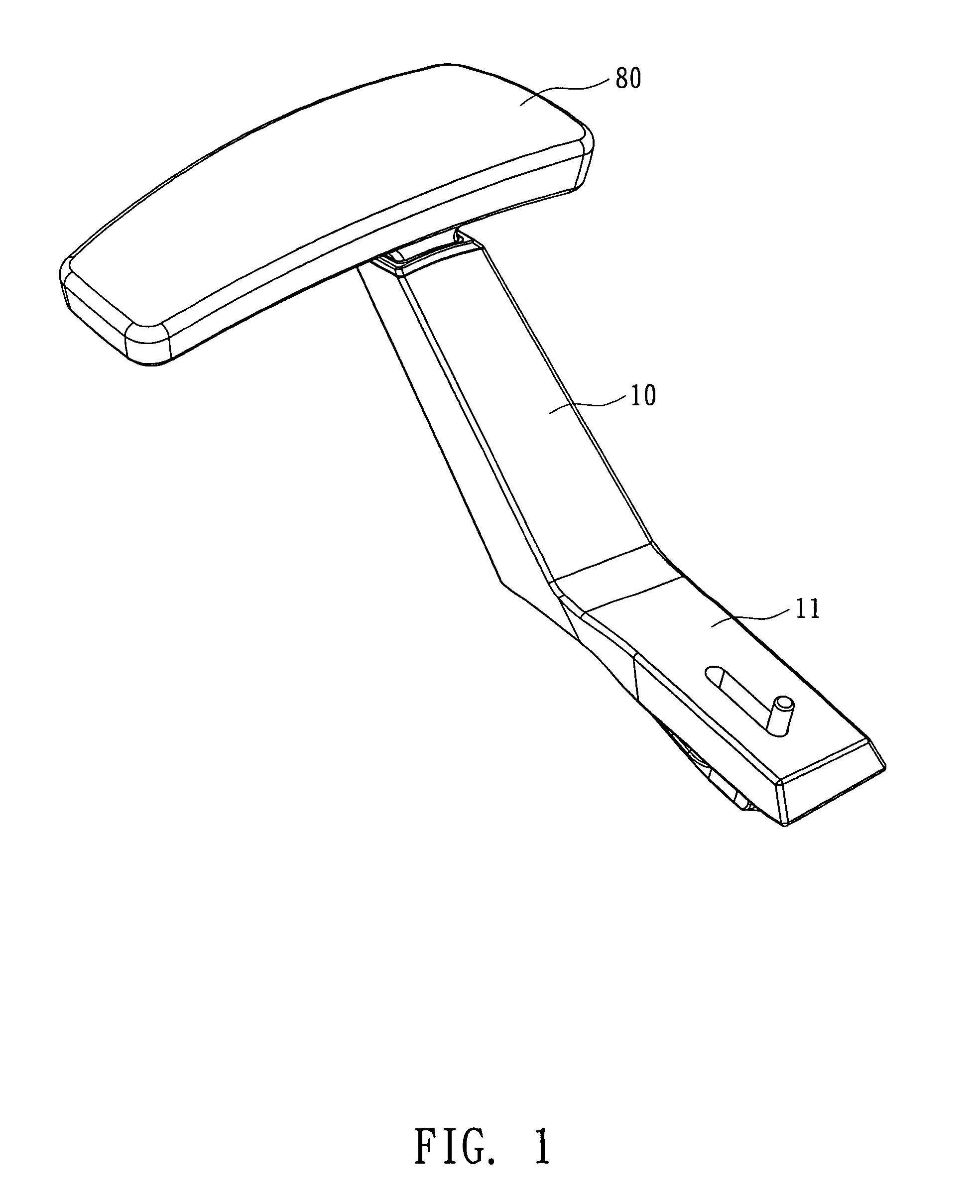
[0016]The sleeve 10 is fastened on a base 11 that is secured on the bottom of a chair. A tubular member 20 is fixed inside top end of the sleeve 10. The tubular member 20 can be either an integrated member, as shown in FIG. 11 or formed by two halves, as shown in FIG. 5. A sliding slot 21 is arranged on inside of the tubular member 20. A plurality of equal-distant parallel locating holes 22 is arranged on inner surface of the sliding slot 21, as shown in FIG. 5&FIG. 6. The slider 30 is inserted in the sliding slot 21 while a concave hole 34 is located at the middle par...


PUM


Abstract

An armrest adjustment mechanism is disclosed. The armrest adjustment mechanism includes a sleeve, a tubular member, a slider, a long plate, a fixing plate, a guiding plate, a retaining block, a lower base, an armrest pad and a lever arm. The armrest adjustment mechanism features on that: an insertion hole is disposed on upper end of the long plate while the lever arm is arranged inside a space between the armrest pad and the lower base. The lever arm inserts through the insertion hole on top end of the long plate so that the long plate hangs on the lever arm, working as a load. One end of the lever arm is arranged on one side of the lower base, working as the fulcrum while the other end of the lever arm is arranged on an opposite side of the lower base correspondingly. A push member projecting from a corresponding opening of the lower base is arranged on the other end of the lever arm, working as the effort. Thus the push member is moved upwards by being pushed by the user from the outside or elastically turned back to the original position so as to make the lever arm (like a Type-2 lever) drives the long plate to move upwards synchronously. Therefore, the adjustment of the armrest height is achieved.

Description

BACKGROUND OF THE INVENTION[0001]The present invention relates to a height adjustment mechanism, especially to a height adjustment mechanism for an armrest that have a lever arm disposed between an armrest pad and a lower base and working like a Type-2 (Class two) lever for adjusting height of the armrest by pushing one end of the lever arm.[0002]There are various designs of the armrest height adjustment mechanism. The inventor of the present invention has invented an armrest height adjustment device and obtained U.S. Pat. No. 6,336,680 HEIGHT-ADJUSTMENT MECHANISM FOR ARMREST, as shown in FIG. 10&FIG. 11. The height adjustment mechanism for an armrest includes a sleeve 10, a tubular member 20, a slider 30, a long plate 40, a fixing plate 50, a guiding plate 60 and a retaining block 70. While adjusting height of the armrest, by pulling up a handle 41 manually, the long plate 40 is moved upwards elastically (the spring 43 is extended simultaneously) so that a projection 45 moves upwar...

Claims


Application Information

Patent Timeline
Patent Type & Authority Patents(United States)
IPC IPC(8): A47C7/54
CPCA47C1/03A47C1/0305
Inventor LEE, CHING-YANG
Owner ISOTECH PRODS
Why Eureka
Try Eureka