Spray gun having improved fluid tip with conductive path

a spray gun and fluid tip technology, applied in the direction of spraying power supply, electric spraying apparatus, burners, etc., can solve the problems of unsatisfactory spray pattern, reduced overall quality of finished product, and airless spray gun not having the hardware needed for air spray operation, so as to enhance the modularity and ease of use of the gun, and reduce operator fatigue

Inactive Publication Date: 2005-04-12
NORDSON CORP
View PDF34 Cites 72 Cited by
  • Summary
  • Abstract
  • Description
  • Claims
  • Application Information

AI Technical Summary

Benefits of technology

In accordance with other aspects of the invention related to the electrostatic technologies, a modular extension is used that houses a high voltage multiplier having a multi-step weight distribution. This positions most of the multiplier weight over the handle to reduce operator fatigue. In accordance with another aspect of the invention, an atomizing component includes an electric circuit path for an electrode, either molded with a fluid tip in the case of a high pressure gun or molded into a needle valve in the case of a low pressure gun. This greatly enhances the modularity and ease of use of the gun for assembly, repair and maintenance. Still a further aspect of the electrostatic version is a dynamic electrostatic seal that isolates the high voltage charge material from ground at the gun body to prevent discharge. Still a further aspect of the invention provides for an air cooled heat sink for the high voltage multiplier.

Problems solved by technology

In both air spray and HVLP spray processes, the atomization air may not fully atomize the fluid or may produce an undesired spray pattern.
This effect can reduce the overall quality of the finished product.
For example, an airless spray gun does not have the hardware needed for air spray operation.
An air assisted airless gun will have air supplied to it, but typically will not operate satisfactorily as a true air spray gun.

Method used


Image

  • Spray gun having improved fluid tip with conductive path
  • Spray gun having improved fluid tip with conductive path
  • Spray gun having improved fluid tip with conductive path

Examples


Embodiment Construction

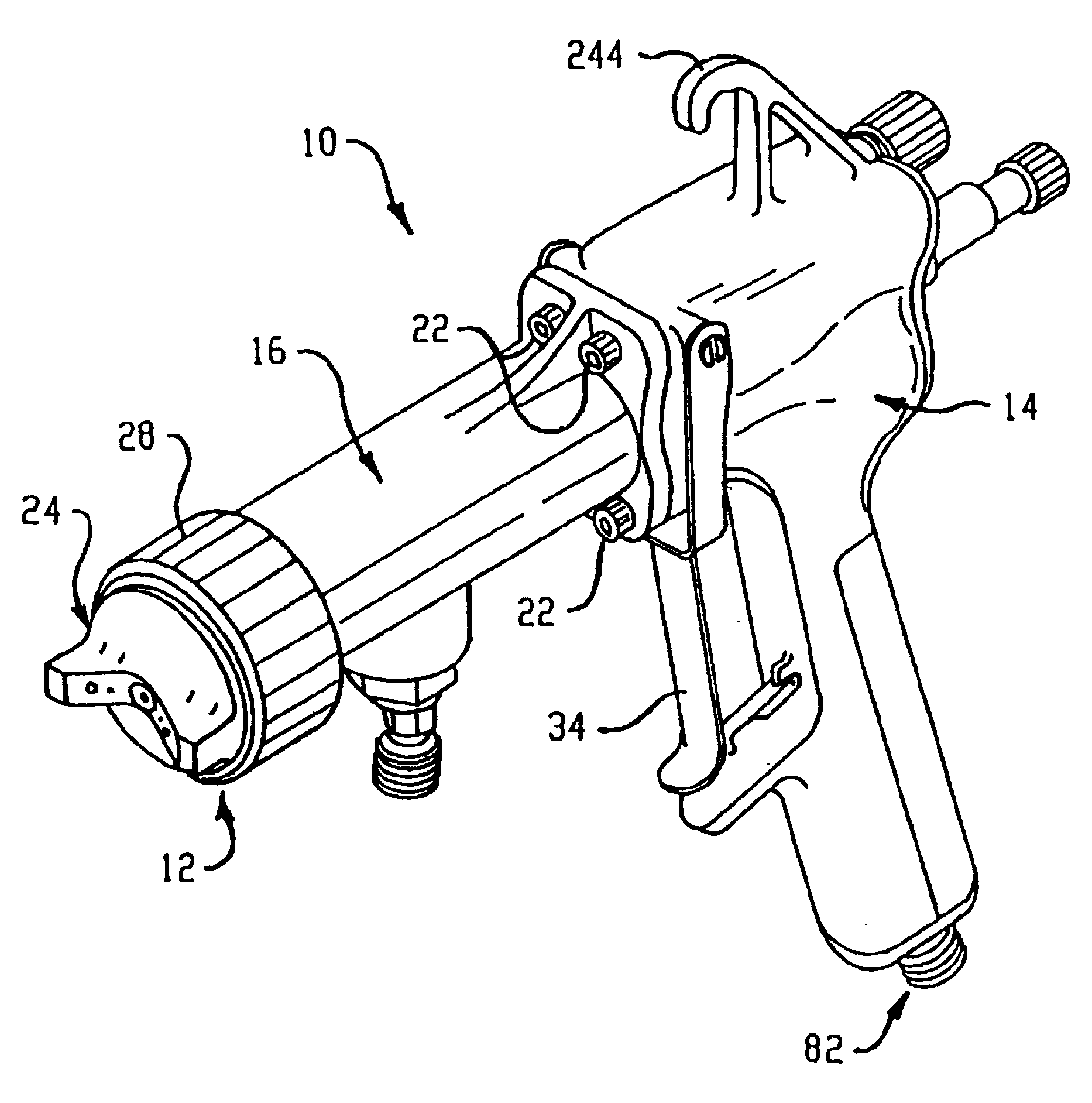
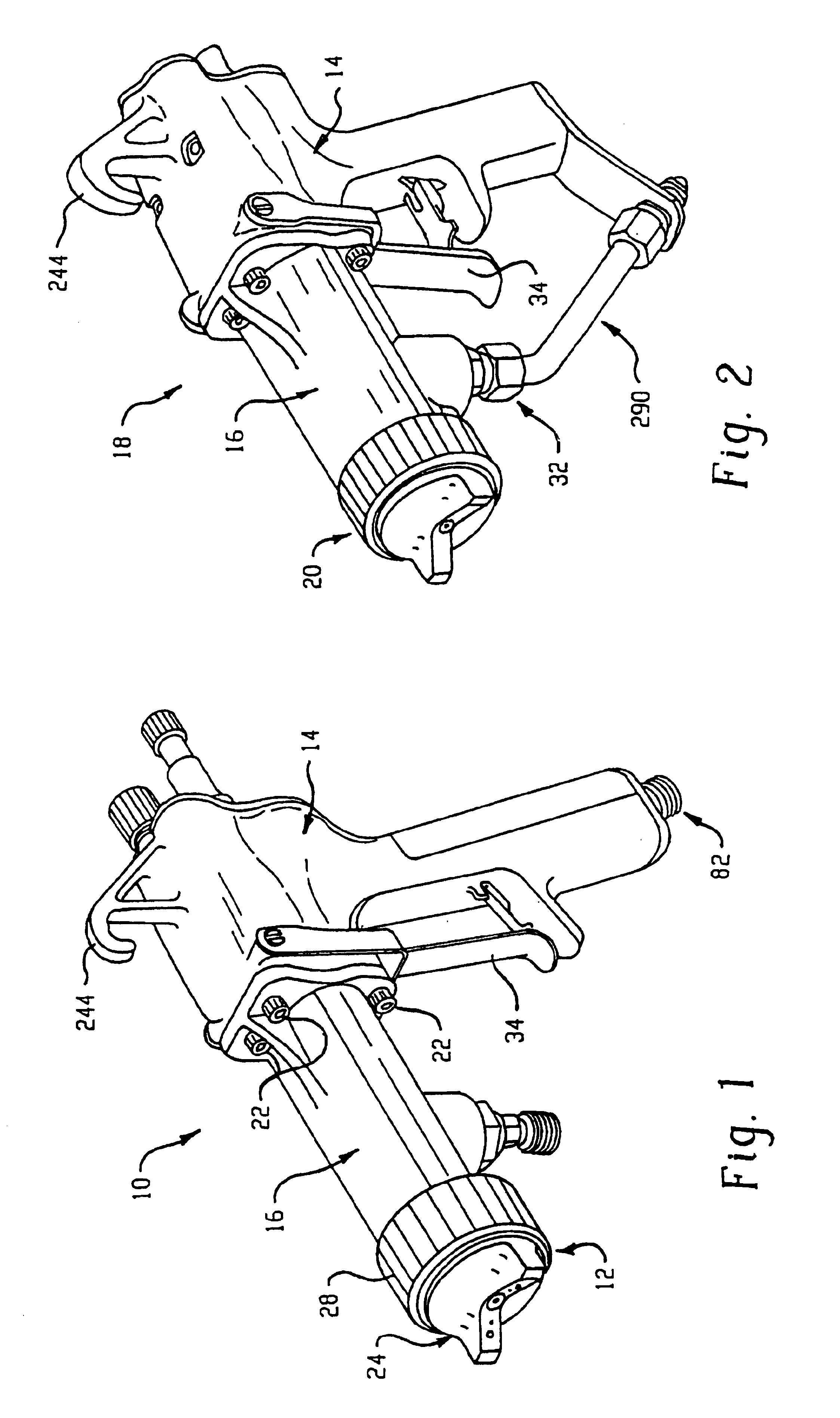
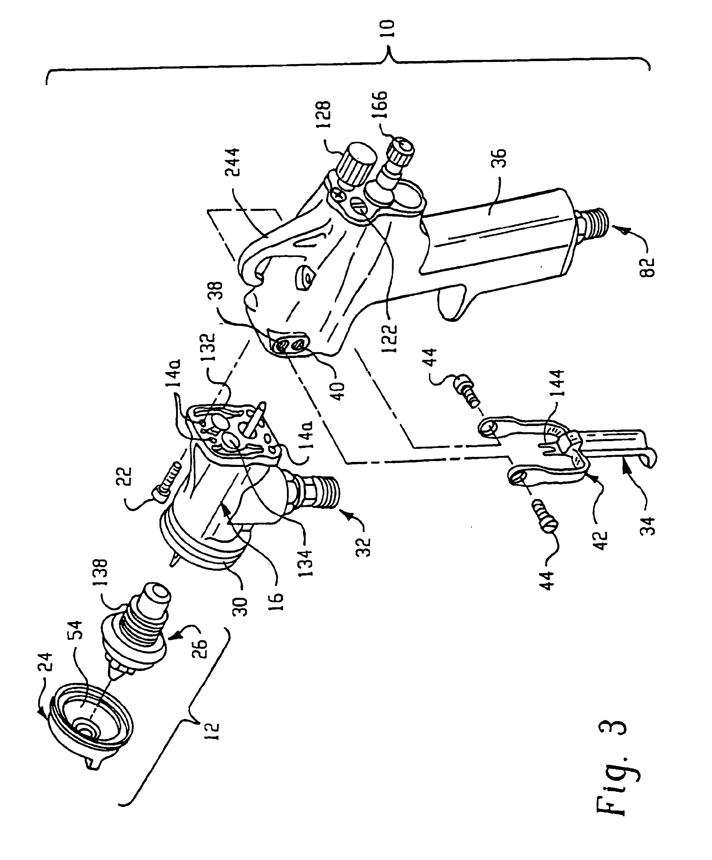
With reference to FIG. 1, the present invention contemplates a modular spray gun 10 that can be easily configured to operate with a selectable spraying process. The invention contemplates a modular spray gun design whereby the gun can operate as an air spray gun, an airless spray gun, an air assisted airless (AAA) spray gun or an HVLP spray gun. These processes are intended to be exemplary in nature in that other spray processes may be available for incorporation into the modular gun concept, for example, an electrostatic spray process. In general, it is within the scope of the present invention to provide a modular spray gun design that can be configured to operate as an airless gun and as an air spray gun. Those skilled in the art will appreciate, for example, that a AAA spraying process is a variation of an airless spray process, and that an HVLP process is a variation of an air spray process. Thus, other variations in these spray processes and the incorporation of other spray pr...


PUM


Abstract

A modular spray gun that can be configured and built to operate using a selectable spray process. The modular spray gun includes a gun body, an extension and a selectable spray atomizing component. The basic gun body and extension are used to configure a spray gun that can operate as an air spray gun, an airless spray gun, an AAA gun or an HVLP spray gun. The modular extension can be selected to allow circulating or non-circulating operation. The modular extension also permits a variety of spray nozzle assemblies to be mounted thereon depending on the selected spray process to be used with the specific gun. The modular gun body allows selective connection of an atomizing air supply and additional components specific to a particular spray process. An indicator device and/or a relief valve is provided for spray guns using an HVLP spray process to provide an indication that the spray gun is in compliance with the maximum nozzle air pressure limit, usually less than 10 psi. A new air valve seal assembly is also provided. The modular gun design can accommodate electrostatic and non-electrostatic versions.

Description

TECHNICAL FIELD OF THE INVENTIONThe present invention relates to fluid spray guns. More particularly, the invention provides a modular design for a fluid spray gun which permits the gun to be configured to operate with a selectable spray process such as airless, air assisted airless, air spray and HVLP, with significantly reduced inventory requirements and minimal parts changes and assembly labor. The gun is provided in an electrostatic and non-electrostatic version.BACKGROUND OF THE INVENTIONFluid spray guns are generally known and are commonly used to spray a wide variety of fluids on any number of different types of articles. Spray guns can be used, for example, to spray fluids such as paint, lacquer, cleansers, sealants and so forth. Fluid spray guns may be hand operated or automatic depending on the specific application system requirements.Fluid spray technology includes a number of spraying modes or spraying processes for applying a fluid to an object. A fundamental characteri...

Claims


Application Information

Patent Timeline
Patent Type & Authority Patents(United States)
IPC IPC(8): B05B5/025B05B7/06B05B5/053B05B7/02B05B9/01B05B7/24B05B7/12B05B9/00B05B1/30B05B7/00B05B5/03B05B7/08B05B12/08B05B1/32B05B12/00
CPCB05B1/3046B05B12/008B05B5/0533B05B7/0081B05B7/02B05B7/066B05B7/12B05B7/1209B05B7/1254B05B7/2489B05B9/01B05B12/002B05B5/0531B05B7/0815B05B5/03B05B7/1263B05B12/0026
Inventor HARTLE, RONALD J.MANCINI, DAVID L.EHRNSCHWENDER, GEORGE C.
Owner NORDSON CORP
Why Eureka
Try Eureka