

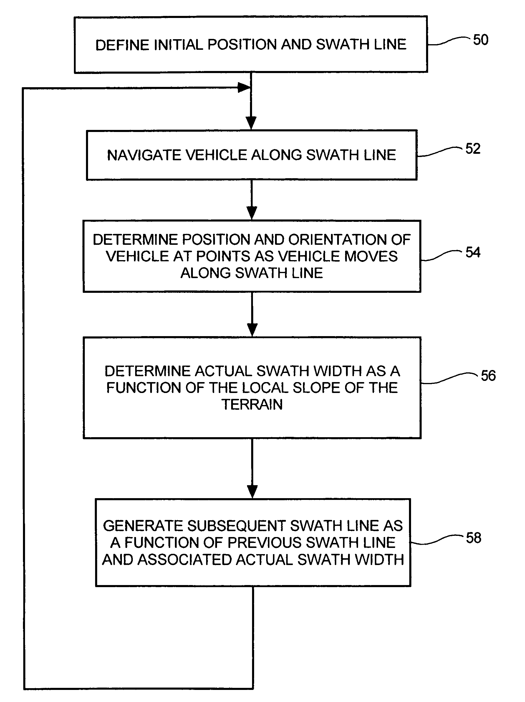
Swath line creation including slope compensation for an automatic guidance system of a work vehicle
a technology of automatic guidance system and swath line, which is applied in the direction of process and machine control, distance measurement, instruments, etc., can solve the problems of overlap of swaths or gaps between swaths, and achieve the effect of reducing operator fatigue and increasing the accuracy of the path of the vehicl
- Summary
- Abstract
- Description
- Claims
- Application Information
AI Technical Summary
Benefits of technology
Problems solved by technology
Method used
Image

Examples
Embodiment Construction
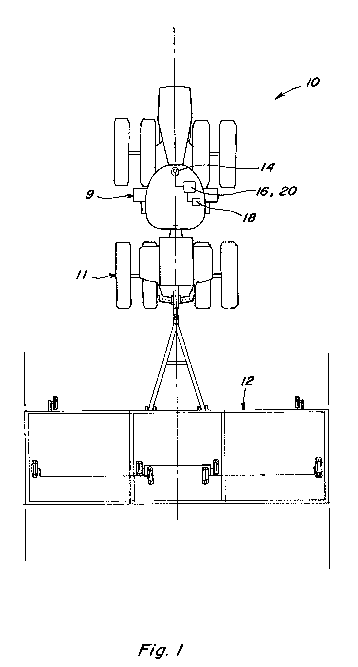
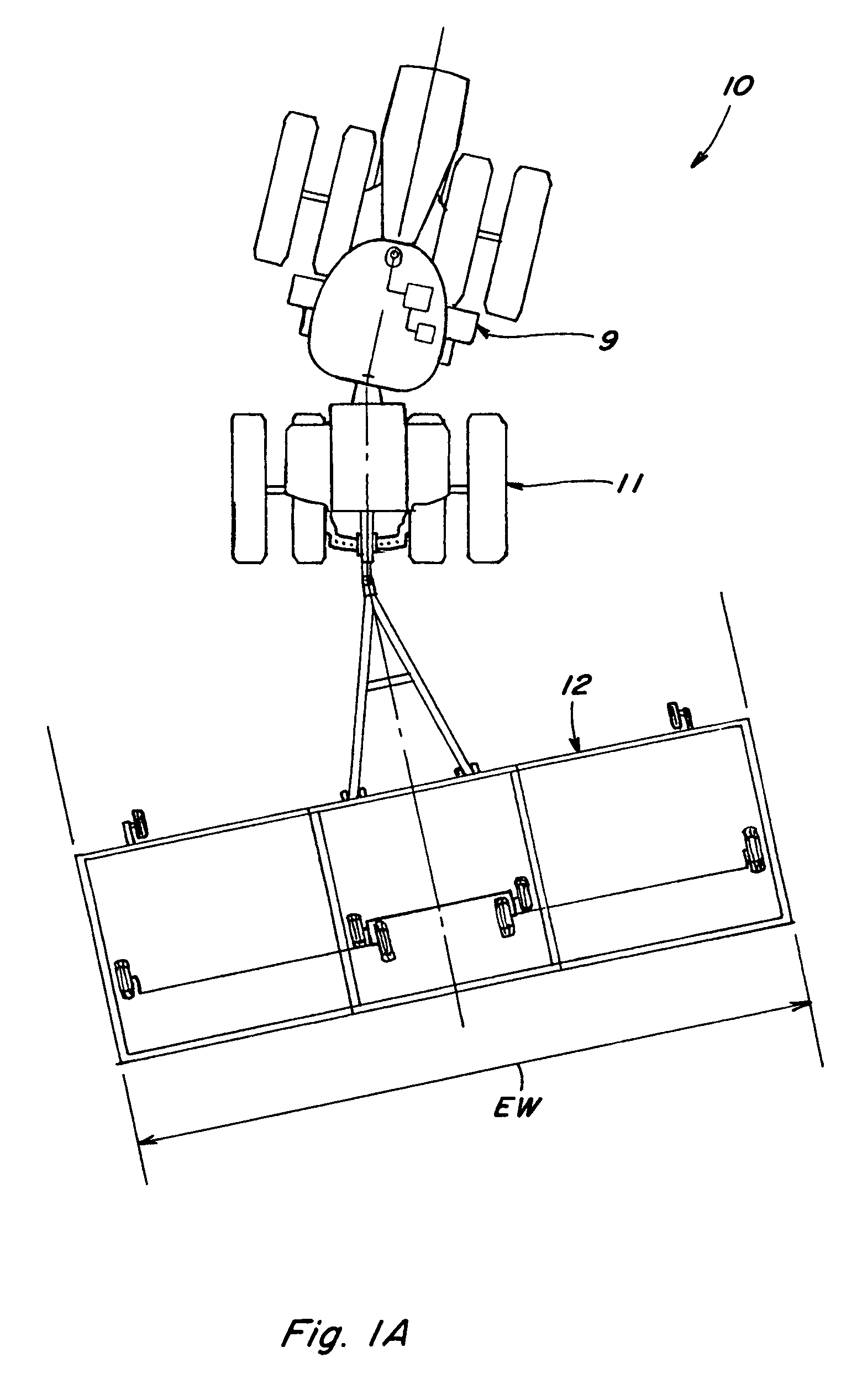
[0023]The swath generation apparatus and methods described herein may find application in precision agriculture systems used to control crop spraying operations, harvesting operations, cultivation and plowing operations, planting and seeding operations, fertilizer application, or other operations where highly accurate positioning information is used in conjunction with defined patterns of swaths to control transit of a vehicle over a land area. Such systems for precision location determination are generally well known and are exemplified by those disclosed in U.S. Pat. Nos. 6,199,000 and 6,553,299, each entitled “Methods and Apparatus for Precision Agriculture Operations Using Real Time Kinematic Global Positioning Systems” which are incorporated herein in their entirety by reference. Although the various methods will be described with particular reference to GPS based systems, it should be appreciated that the teachings are equally applicable to control systems using other methods ...
PUM
 Abstract
Description
Claims
Application Information