Pneumatic motor trigger actuator

a technology of trigger actuator and pneumatic motor, which is applied in the field of pneumatic tools, can solve the problems of requiring as long as six minutes to complete a single drilling cycle in this manner, hand and wrist fatigue, and length of time, and achieve the effect of greatly reducing operator fatigue and increasing safety and efficiency

Active Publication Date: 2005-09-01
THE BOEING CO
View PDF13 Cites 12 Cited by
  • Summary
  • Abstract
  • Description
  • Claims
  • Application Information

AI Technical Summary

Benefits of technology

[0005] By eliminating the need for an operator to continuously hold down the pneumatic motor trigger throughout a drilling operation, operator fatigue is greatly reduced. Additionally, automatic shutoff and emergency shutoff of the drilling cycle greatly increased safety and efficiency.

Problems solved by technology

While not necessarily significant under some conditions, when drilling through materials often used in the aerospace industry, it may take as long as six minutes to complete a single drilling cycle in this manner.
The constant pressure maintained by the operator throughout a long drilling cycle may potentially cause hand and wrist fatigue.
While these solutions may reduce the length of time required to maintain pressure on the trigger, the operator is still required to initially depress the trigger and then perform additional operations.
Accordingly, significant hand and wrist fatigue still occur during repetitive and cyclical use of a hand held drilling unit.
Moreover, with these prior solutions, the operator is required to disengage the rotating attachment or engagement buttons at the end of each use.

Method used


Image

  • Pneumatic motor trigger actuator
  • Pneumatic motor trigger actuator
  • Pneumatic motor trigger actuator

Examples


Embodiment Construction

[0019] The following description of the preferred embodiment(s) is merely exemplary in nature and is in no way intended to limit the invention, its application, or uses.

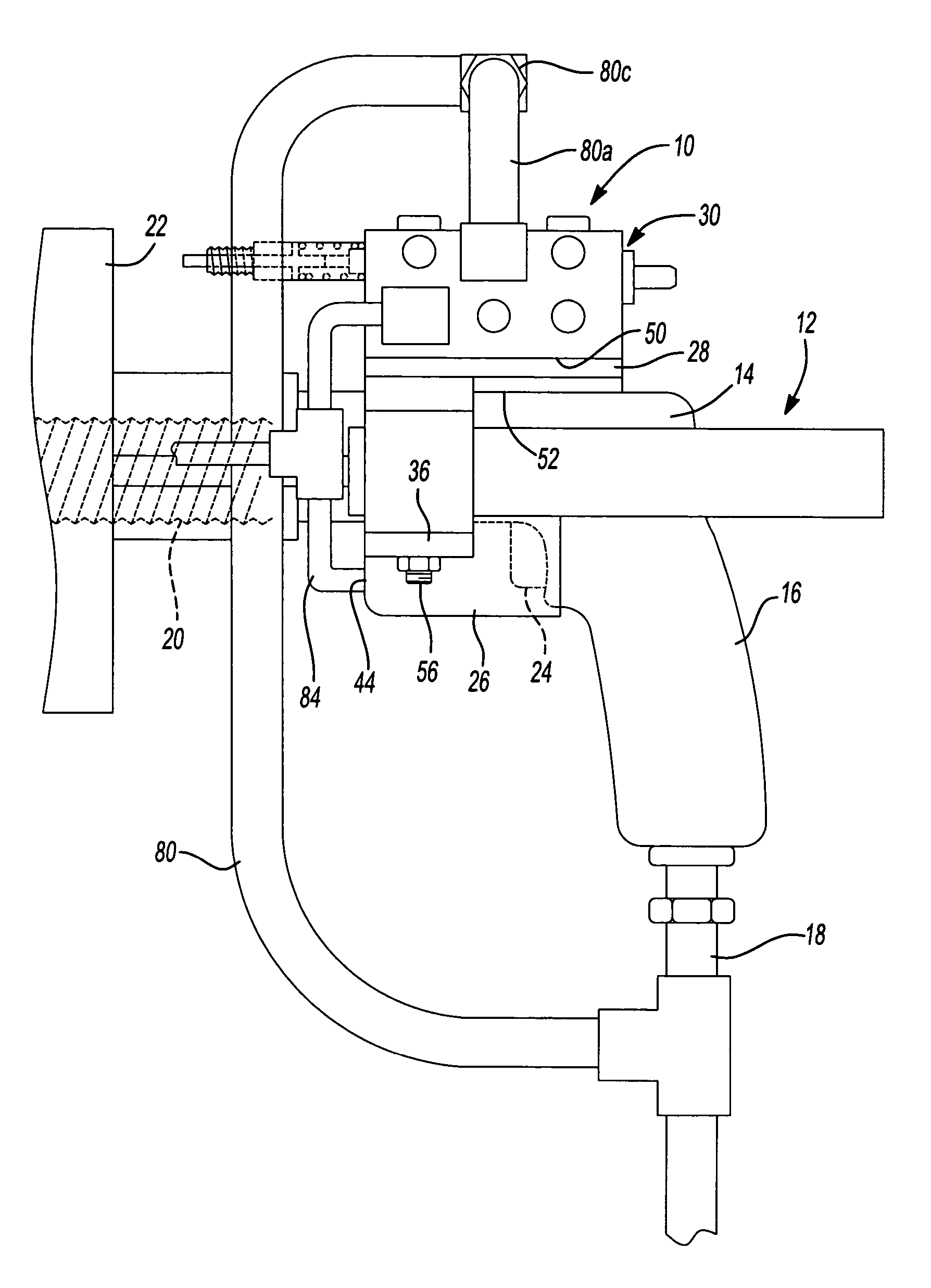
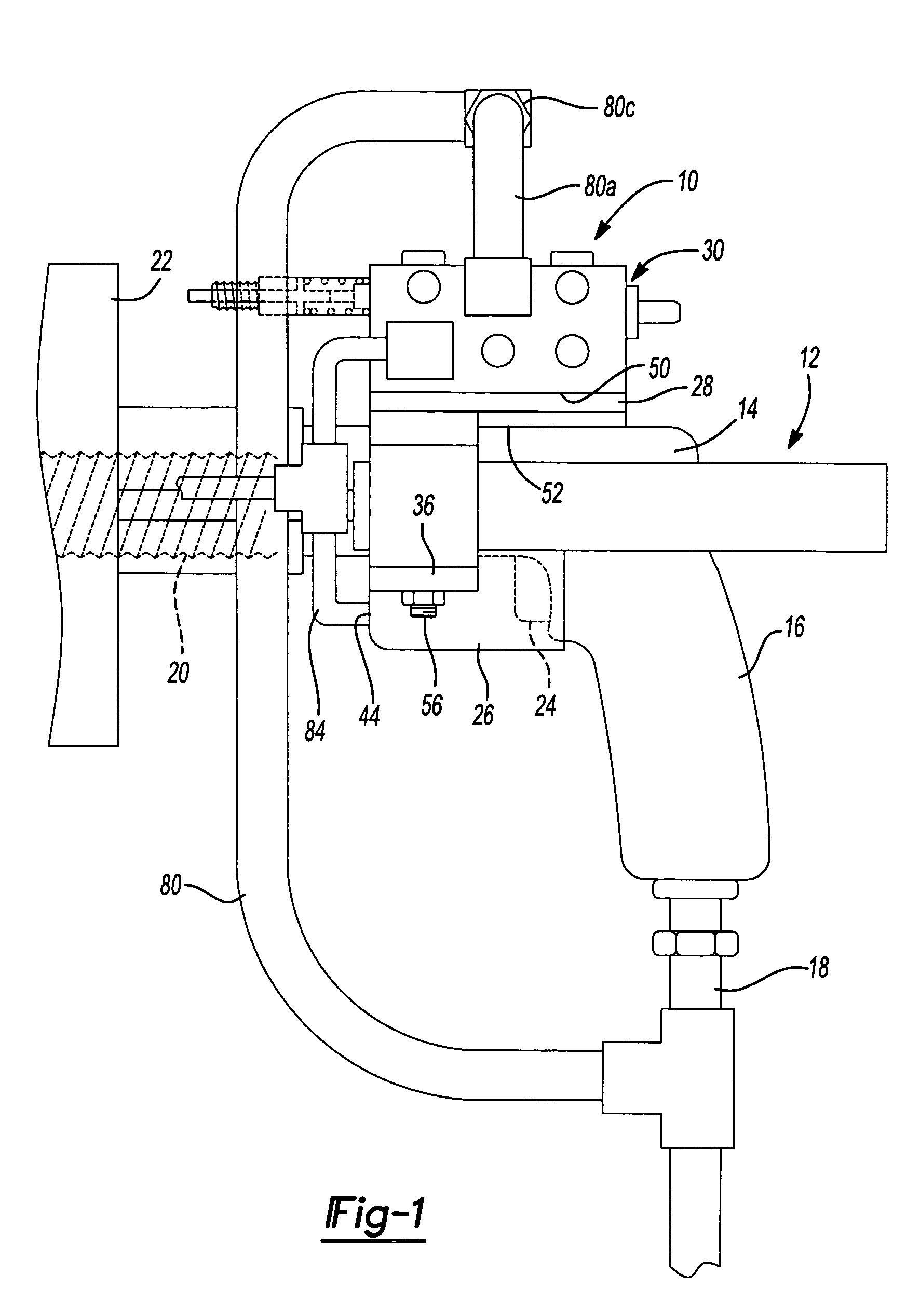
[0020] With reference to FIG. 1, a preferred embodiment of a pneumatic motor trigger actuator (hereinafter “trigger actuator”) 10 constructed according to the principles of the present invention is shown in operative association with an exemplary pneumatic drill 12. The pneumatic drill 12 generally includes a motor housing 14 with a handle 16 extending therefrom. The motor housing 14 contains a pneumatic motor (not shown) located therein. An air input tube 18 is coupled to the pneumatic drill 12 at the handle 16. The air input tube 18 provides compressed air flow to the pneumatic motor (not shown) of the pneumatic drill 12 from a compressed air source (not shown).

[0021] The pneumatic drill 12 further includes a drill bit 20 extending out from the motor housing 14. The drill bit 20 is rotationally driven by the pneu...


PUM

PropertyMeasurementUnit
air pressureaaaaaaaaaa
forceaaaaaaaaaa
drill depthaaaaaaaaaa

Abstract

A pneumatic motor trigger actuator includes a trigger housing adapted to engage a pneumatic motor trigger of a pneumatic tool. A top plate is coupled to the trigger housing. A primary valve is coupled to the top plate and has an open configuration and a closed configuration. The primary valve is pneumatically coupled to the trigger housing such that air flow through the primary valve, when the primary valve is in the open configuration, enters the trigger housing and causes a plug to physically engage the motor trigger with sufficient force to move it to is fully engaged position. The primary valve includes a primary switch and an automatic stop switch. The primary switch is engagable by an operator to configure the primary valve in the open configuration. The automatic switch is engagable by an object to move the primary valve to the closed configuration when a predetermined condition is met.

Description

FIELD OF THE INVENTION [0001] The present invention relates to pneumatic tools, and more particularly to a pneumatic motor trigger actuator for a pneumatic tool. BACKGROUND OF THE INVENTION [0002] Pneumatic tools are common throughout industry and are used in a wide variety of manufacturing settings. For example, pneumatic tools are prelevant in the aircraft manufacturing industry. One typical pneumatic tool used in the aircraft manufacturing industry is a hand held drilling unit. When drilling through an aircraft structure using a hand held drilling unit, an operator must maintain positive finger pressure against the start trigger of the drilling unit throughout the entire drilling cycle. While not necessarily significant under some conditions, when drilling through materials often used in the aerospace industry, it may take as long as six minutes to complete a single drilling cycle in this manner. Upon releasing the trigger, the trigger returns to its rest position and the pneumat...

Claims


Application Information

Patent Timeline
Patent Type & Authority Applications(United States)
IPC IPC(8): B23B45/00B23B47/00B25D1/00
CPCB23B47/00B23B45/003
Inventor MARTIN, SCOTT A.BLANKENSHIP, THOMAS O.MORRISON, JAMES L.
Owner THE BOEING CO
Why Eureka
Try Eureka