Pneumatic crimping and capping handheld tool

a handheld tool and pneumatic technology, applied in the field of pneumatic crimping and capping tools, can solve the problems of crimping and decapping, soon tireing the user, etc., and achieve the effect of reducing operator fatigu

Inactive Publication Date: 2004-05-04
MARSHALL KENNETH EDWARD
View PDF15 Cites 13 Cited by
  • Summary
  • Abstract
  • Description
  • Claims
  • Application Information

AI Technical Summary

Benefits of technology

The Applicant has devised a stand-mounted crimper-decapper press tool--the subject of GB 2,213,137--featuring an adjustable work unit cradle, using a long operating arm to afford significant mechanical advantage, and so alleviate operator fatigue.

Problems solved by technology

Hitherto known crimpers and decappers suffer from various operational disadvantages--one being that they can soon tire the user, in repetitive operation.
This reflects adverse tool ergonomics, such as excessive weight or bulk, inappropriate leverage--ie mechanical advantage, required manual force and attendant handle travel--and geometry--ie path of hand movement.

Method used


Image

  • Pneumatic crimping and capping handheld tool
  • Pneumatic crimping and capping handheld tool
  • Pneumatic crimping and capping handheld tool

Examples


Embodiment Construction

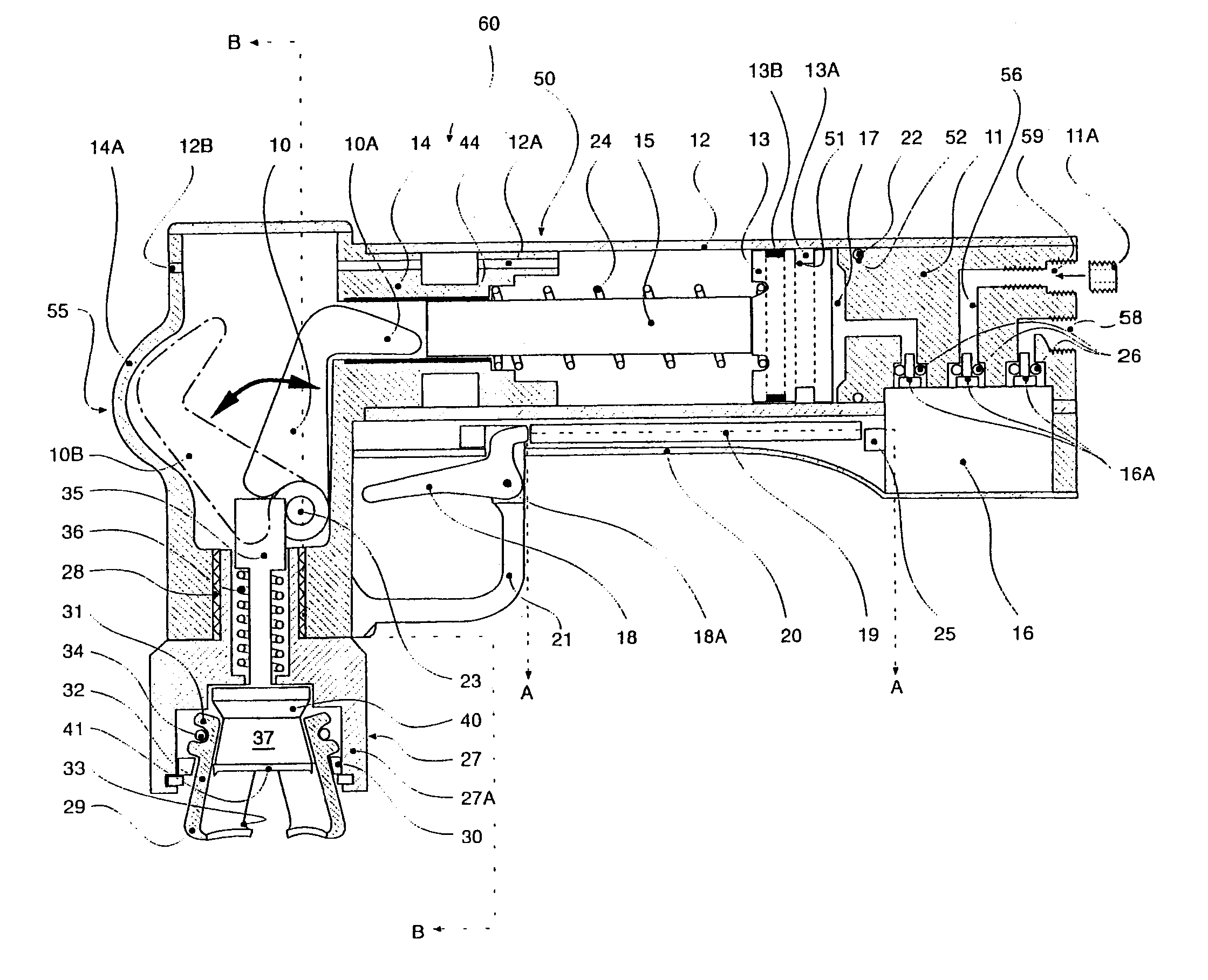
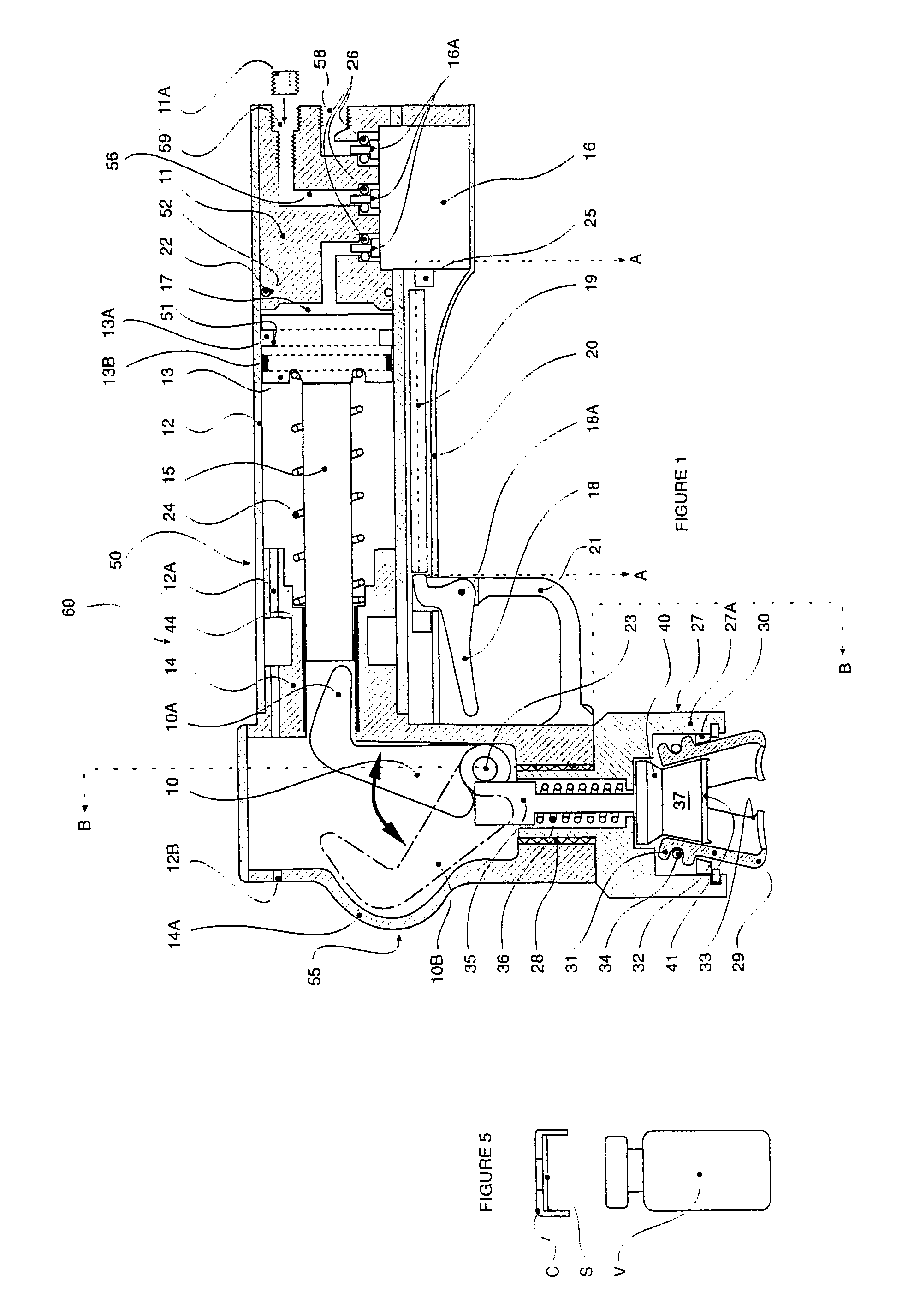
Referring to FIG. 1, a hand-held, power-operated (or power-assisted) crimper and de-capper tool 60 is of overall `L`-shaped configuration, with an elongate handle body 50 and angularly offset tool head 55, for a demountable crimper or decapper tool unit 27.

The tool 60 incorporates an internal fluid actuator, in this case pneumatic--for compatibility with compressed air supplies commonly available in light industrial and laboratory environments.

The handle body 50 comprises an elongate hollow tubular sleeve or barrel housing 12, upon one (forward) end of which is mounted the tool head 55.

An external operating trigger 18 is disposed in the quadrant between the handle body 50 and head 55.

The housing 12 is preferably of a lightweight material, such as aluminium tubing--of a diameter such that a small adult hand can wrap (comfortably) around it.

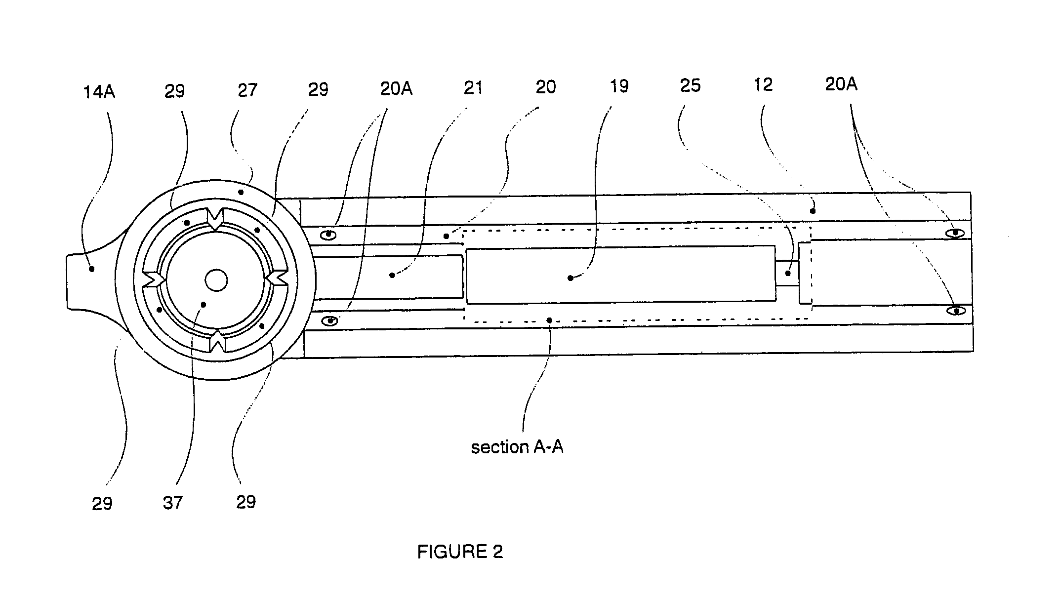
The housing 12 forms a containment cylinder for a piston-in-cylinder fluid actuator, with a linearly slidable (reciprocating) piston 13 located co...


PUM

PropertyMeasurementUnit
pressureaaaaaaaaaa
lengthaaaaaaaaaa
sizesaaaaaaaaaa

Abstract

A hand-held, power-operated or power-assisted, crimping/er or decapping/er tool (60), for container closures, such as vial caps (C), has a hollow handle (50), housing a (pneumatic) piston-in-cylinder actuator (12, 13), with an external trigger (18) operating an internal control valve (16), to control connection of an external pressure supply, through an internal distribution block (11), and displacement of an actuator output rod (15), coupled, through a pivoted bell crank lever (10), to a demountable crimping/er or decapping/er (27).

Description

BACKGROUND OF INVENTION1. Field of InventionThe present invention relates to a so-called `crimping / er` and `decapping / er` tool--particularly, but not exclusively, for container closures, such as used for sample vials, atomisers, infusion bottles and the like.The closure is typically a circular cap, with a depending annular peripheral skirt, which forms a (mechanically secure) circumferential edge joint or seal with a (upstanding) neck of a container access opening.TerminologyCrimpingThe term `crimping` is used herein to embrace the (re-) shaping of a deformable (wall) element, say of thin sheet material--by locally applied force--such as to bring the element profile into (close) conformity with a (rigid) contact surface.In this way, intimate--indeed sealing--joint engagement can be achieved.Moreover, a continuous peripheral edge seal can be effected around the circumferential rim of an access opening or mouth--vis to a container--in a singe (re-) shaping action.DecappingSimilarly, t...

Claims


Application Information

Patent Timeline
Patent Type & Authority Patents(United States)
IPC IPC(8): B67B7/00B67B7/16
CPCB67B7/164
Inventor MARSHALL, KENNETH EDWARD
Owner MARSHALL KENNETH EDWARD
Why Eureka
Try Eureka