Method and system for batch manufacturing of spring elements

a spring element and batch manufacturing technology, applied in the field of spring element batch manufacturing, can solve the problems of unsuitable for accommodating electronic components with normal positional variations, difficult manufacturing, and difficult manufacturing of conventional interconnect devices,

Inactive Publication Date: 2010-07-20
NEOCONIX INC
View PDF314 Cites 68 Cited by
  • Summary
  • Abstract
  • Description
  • Claims
  • Application Information

AI Technical Summary

Problems solved by technology

Conventional interconnect devices, such as stamped metal springs, bundled wire, and injection molded conductive adhesives, become difficult to manufacture as the dimensions are scaled down.
Stamped metal spring elements, in particular, become brittle and difficult to manufacture as the dimensions are scaled down, rendering them unsuitable for accommodating electronic components with normal positional variations.
At this size, spring elements made by existing manufacturing technologies become even more brittle and less elastic and cannot accommodate normal variations in system coplanarity and positional misalignments with a reasonable insertion force of about 30 to 40 grams per contact.

Method used


Image

  • Method and system for batch manufacturing of spring elements
  • Method and system for batch manufacturing of spring elements
  • Method and system for batch manufacturing of spring elements

Examples


Embodiment Construction

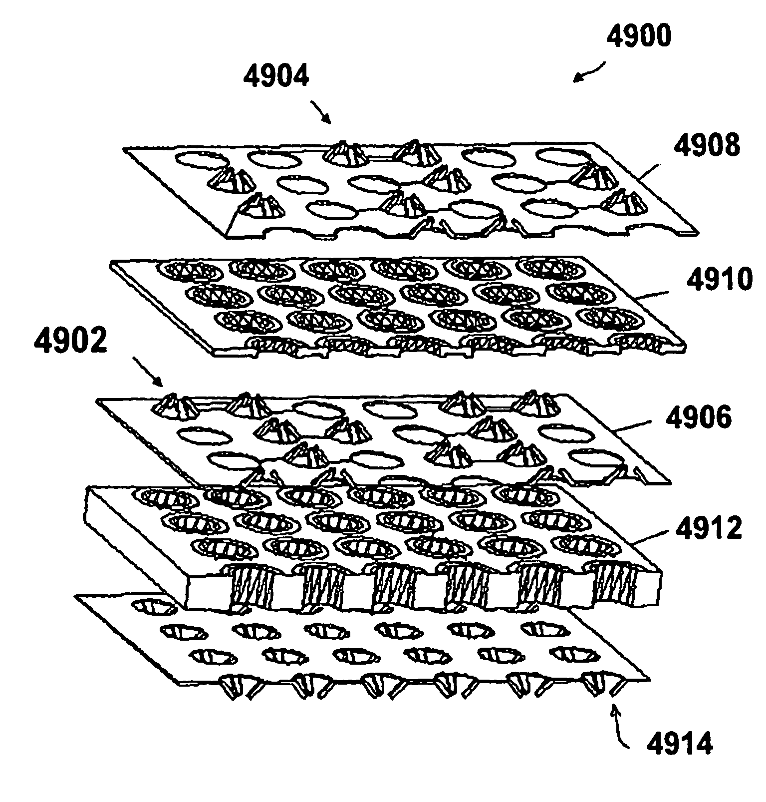
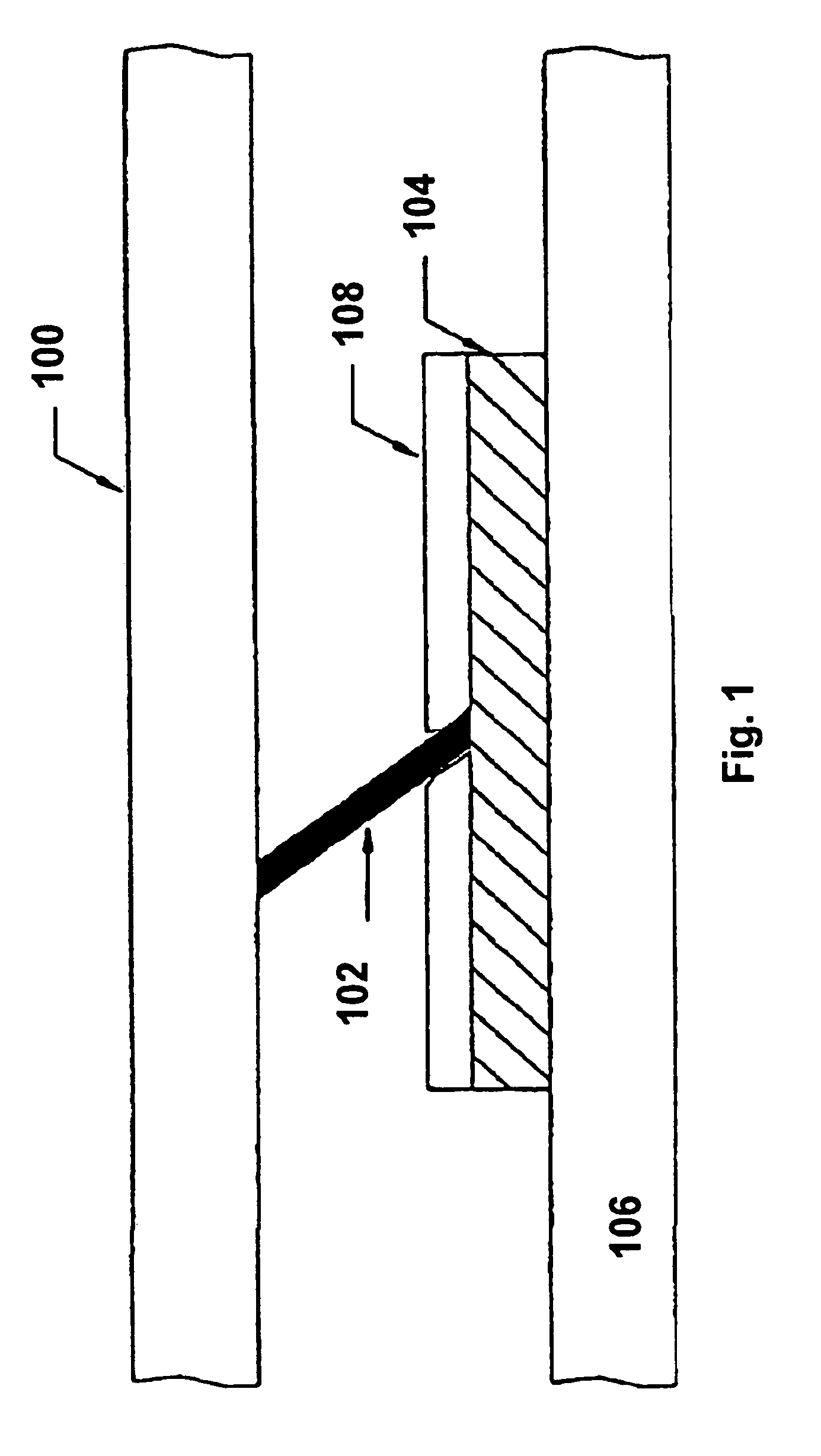
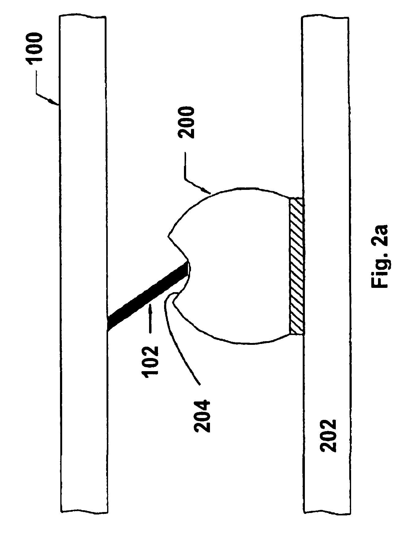
[0096]Aspects of the present invention are related to methods for fabricating electrical connectors by lithographic patterning of metallic layers to form an array or arrays of contact elements. The metallic layers can be applied to a connector substrate before patterning to form the contact elements, or can be free standing layers that are subjected to patterning before joining to the connector substrates. In general, the contacts can be formed from a single layer of metallic material, but can also be formed from multiple layers of the same material, or of different materials, in which one or more layers can be added to the contacts after a metallic layer is patterned to form a contact array. Connectors formed by these methods include substrates having a contact array disposed on a single side, or having contact arrays disposed on both sides, such as interposers.

[0097]Connector elements and interposer layers fabricated according to aspects of the present invention can be produced us...


PUM


Abstract

A system for batch forming a sheet of spring elements in three dimensions is described. A spring element sheet containing spring elements defined in two dimensions is arranged between two mating die press plates. A force is applied to the mating die press plates to form the two-dimensional spring contact elements into three dimensions. Alternatively, configurable die press plates are used to selectively form a two-dimensional spring element sheet into three-dimensional spring contacts.

Description

[0001]This applications is a continuation-in-part of U.S. patent application Ser. No. 11 / 083,031, filed Mar. 18, 2005, now U.S. Pat. No. 7,597,561 which is incorporated herein by reference in its entirety for all purposes and which in turn is a continuation-in-part of U.S. patent application Ser. No. 10 / 412,729, filed Apr. 11, 2003 now U.S. Pat. No. 7,056,131.[0002]This application is also a continuation-in-part of U.S. patent application Ser. No. 11 / 445,272, filed Jun. 2, 2006, which is incorporated herein by reference in its entirety for all purposes and which in turn is a continuation-in-part of U.S. patent application Ser. No. 10 / 412,729, filed Apr. 11, 2003, now U.S. Pat. No. 7,056,131 and is a continuation in part of U.S. patent application Ser. No. 10 / 731,213 filed Dec. 8, 2003 now abandoned.[0003]This application is also a continuation-in-part of U.S. patent application Ser. No. 11 / 649,052 filed Jan. 3, 2007 now U.S. Pat. No. 7,371,073 which is incorporated herein by referen...

Claims


Application Information

Patent Timeline
Patent Type & Authority Patents(United States)
IPC IPC(8): H01R12/00
CPCH01R43/16
Inventor BROWN, DIRK DEWARWILLIAMS, JOHN DAVIDLONG, WILLIAM B.CHEN, TINGBAO
Owner NEOCONIX INC
Why Eureka
Try Eureka