Torque-limiting device

a technology of torque limiter and torque limiter, which is applied in the direction of wrenches, medical science, surgery, etc., can solve the problems of cumbersome recalibration and must be done routinely

Active Publication Date: 2010-07-27
ECA MEDICAL INSTR
View PDF9 Cites 46 Cited by
  • Summary
  • Abstract
  • Description
  • Claims
  • Application Information

AI Technical Summary

Problems solved by technology

Recalibration is a cumbersome task but must be done routinely.
It has, however, been a challenge to develop a reliable disposable driver capable of imparting higher torques for larger applications.

Method used


Image

  • Torque-limiting device
  • Torque-limiting device
  • Torque-limiting device

Examples


Embodiment Construction

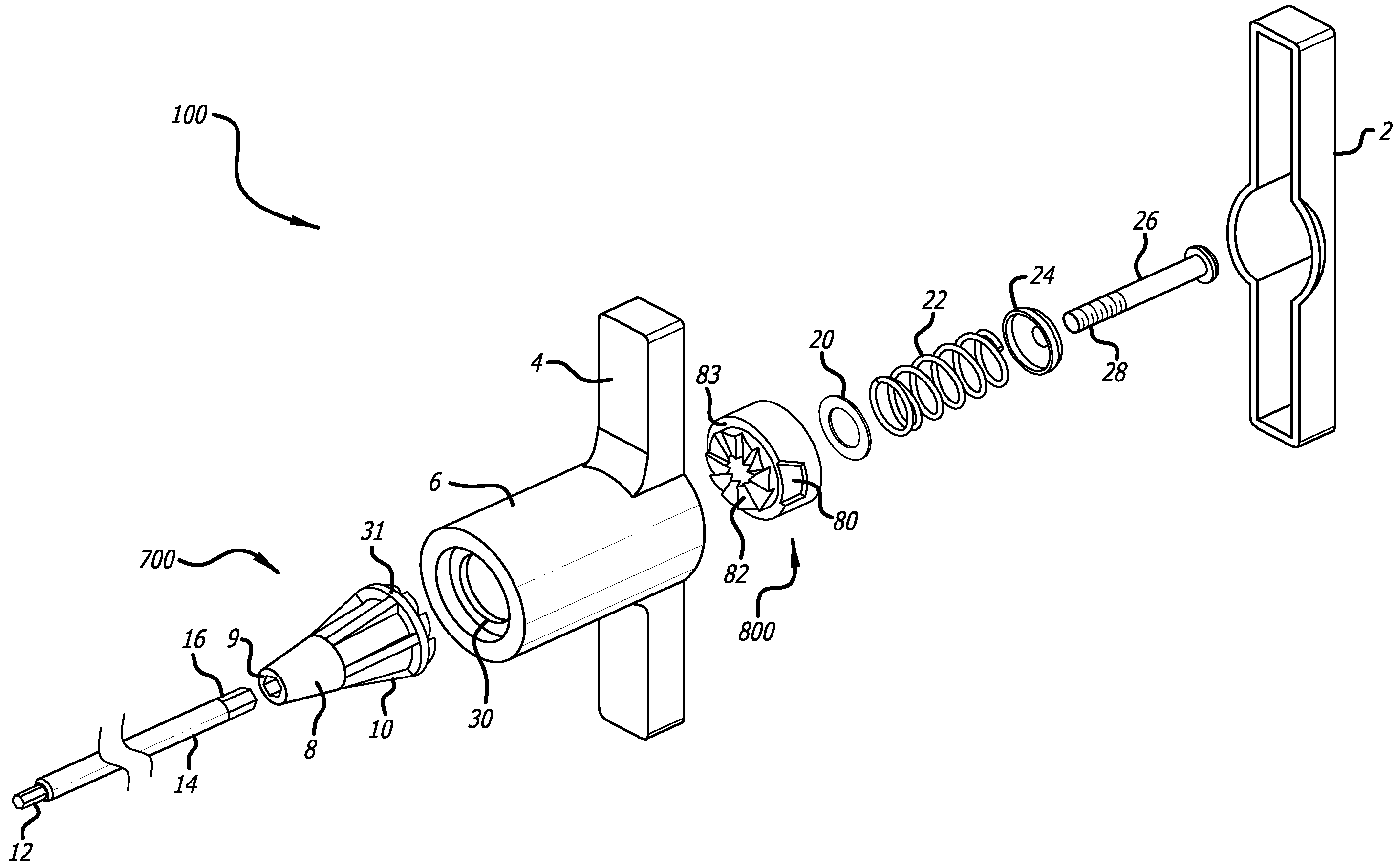
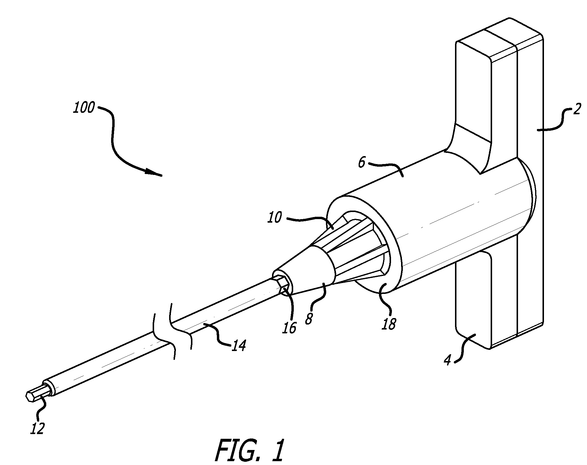
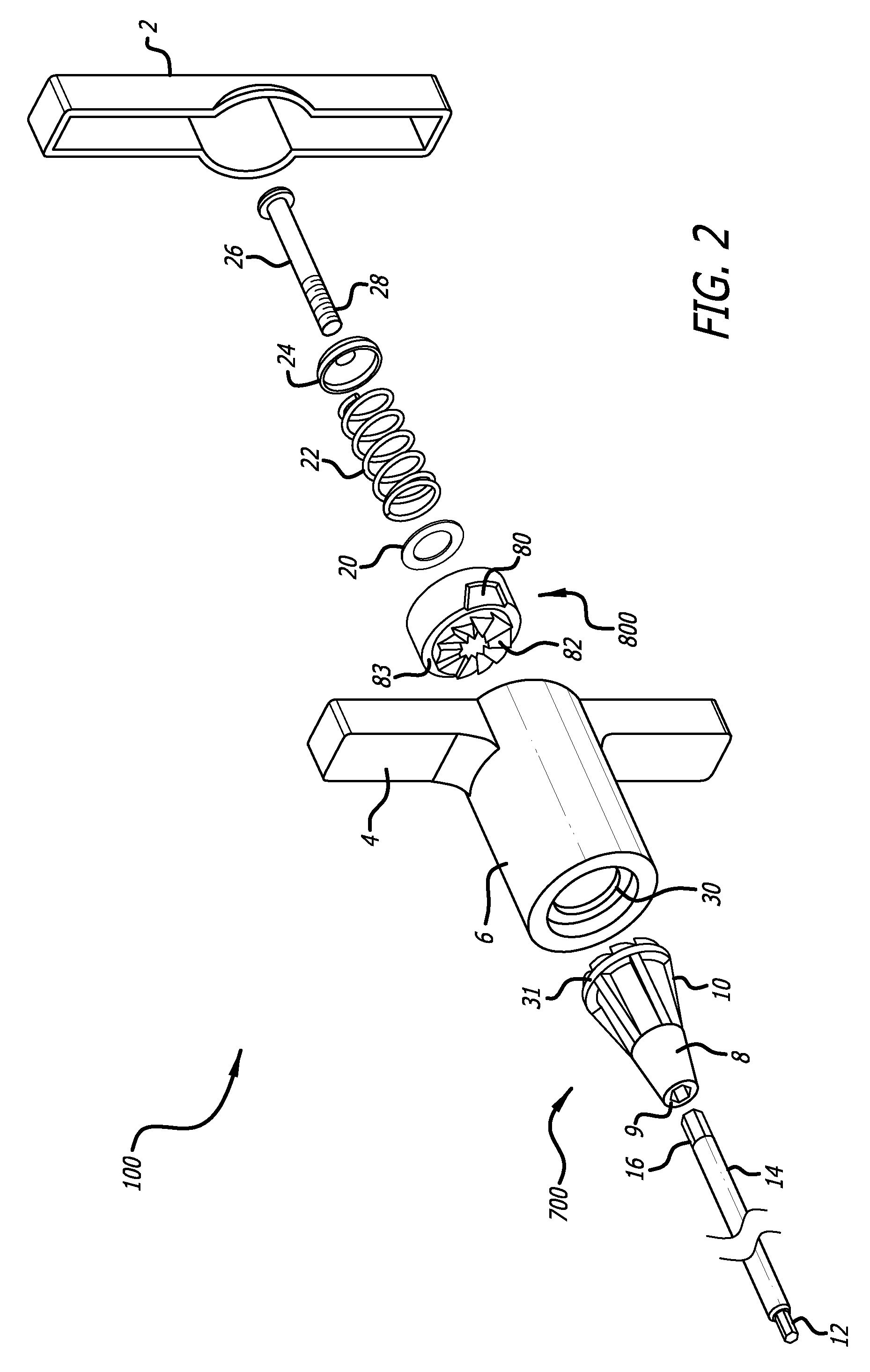
[0022]Referring to FIGS. 1-8, there is a torque-limiting driver 100. The torque-limiting driver 100 has a generally T-shaped handle. The T-shaped handle includes arms 4 at one end an axially extending generally hollow cylindrical body 6, a cup 2 that covers the same end of the T-shaped handle and a cylindrical end 18 opposite the T-shaped handle on the cylindrical body 6. The cup 2 may be snap-fitted to the cylindrical body 6, or may be welded, or attached by any equivalent thereof and the body is preferably molded from a plastic or other economical equivalents.

[0023]At the cylindrical end 18, there is a lower shank 700 that has and annularly tapering body and a nose cone 8 along its length. The lower shank 700 may have a plurality of support flanges 10 that add strength while saving material. At one end, the lower shank 700 tapers to an axial bore 9 at the end of the nose cone 8 molded to engage a shaft 14. The shaft 14 may be hexagonal or cylindrical in transverse cross-sectional ...


PUM


Abstract

A torque-limiting driver has a handle, a body, a torque-limiting assembly and a work-piece engaging tip. The torque-limiting assembly includes an upper and lower shank that have a plurality of teeth circumferentially spaced. The teeth have a vertical face, and inclined face and a flat peak. The inclined face is defined by a radius of curvature that transitions to the flat peak. There is a spring for applying pressure across the upper and lower shank. The teeth engage for relative rotation when the handle is turned and disengage when a predetermined value of torque is exceeded.

Description

BACKGROUND[0001]1. Field[0002]This disclosure relates to a medical use driver tool and, in particular, to a torque-limiting driver that disengages at a predefined torque limit.[0003]2. General Background[0004]Torque-limiting drivers are widely used throughout the medical industry. These torque-limiting drivers have a factory pre-set torque to ensure the accuracy and toughness required to meet a demanding surgical environment.[0005]The medical industry has made use of both reusable and disposable torque-limiting drivers. In a surgical context, there is little room for error and these drivers must impart a precise amount of torque.[0006]Reusable drivers require constant recalibration to ensure that the driver is imparting the precise amount of torque. Recalibration is a cumbersome task but must be done routinely.[0007]Disposable drivers are an easy to use and reliable alternative to the reusable drivers. Typically, each implant, for example, is packaged with a disposable driver design...

Claims


Application Information

Patent Timeline
Patent Type & Authority Patents(United States)
IPC IPC(8): B25B23/157
CPCB25B15/02B25B23/1427A61B2019/301A61B2090/031
Inventor NINO, JOHNIVINSON, DAVID
Owner ECA MEDICAL INSTR
Why Eureka
Try Eureka