
Electromagnetic probe device

a technology of electromagnetic probes and magnetic fields, applied in the direction of filtration separation, instruments, separation processes, etc., can solve the problems of cumbersome prior art magnetic mixing tools, difficult to modify and control the strength of the magnetic field without replacing the magnets, and the use of fixed bulky bar magnets

Inactive Publication Date: 2010-07-27
BOARD OF SUPERVISORS OF LOUISIANA STATE UNIV & AGRI & MECHANICAL COLLEGE
View PDF2 Cites 7 Cited by
  • Summary
  • Abstract
  • Description
  • Claims
  • Application Information

AI Technical Summary

Problems solved by technology

However, in prior art magnetic separation / stirring technologies, fixed bulky bar magnets are used.
These prior art magnetic mixing tools are cumbersome and the strength of the magnetic field is difficult to modify and control without replacing the magnets.
These tools lack compactness and could not be used to move ferrofluids in vivo (for purposes of this application, a ferrofluid is a flowable substance where a portion of the substance is responsive to a magnetic field).

Method used


Image

  • Electromagnetic probe device
  • Electromagnetic probe device
  • Electromagnetic probe device

Examples


Embodiment Construction

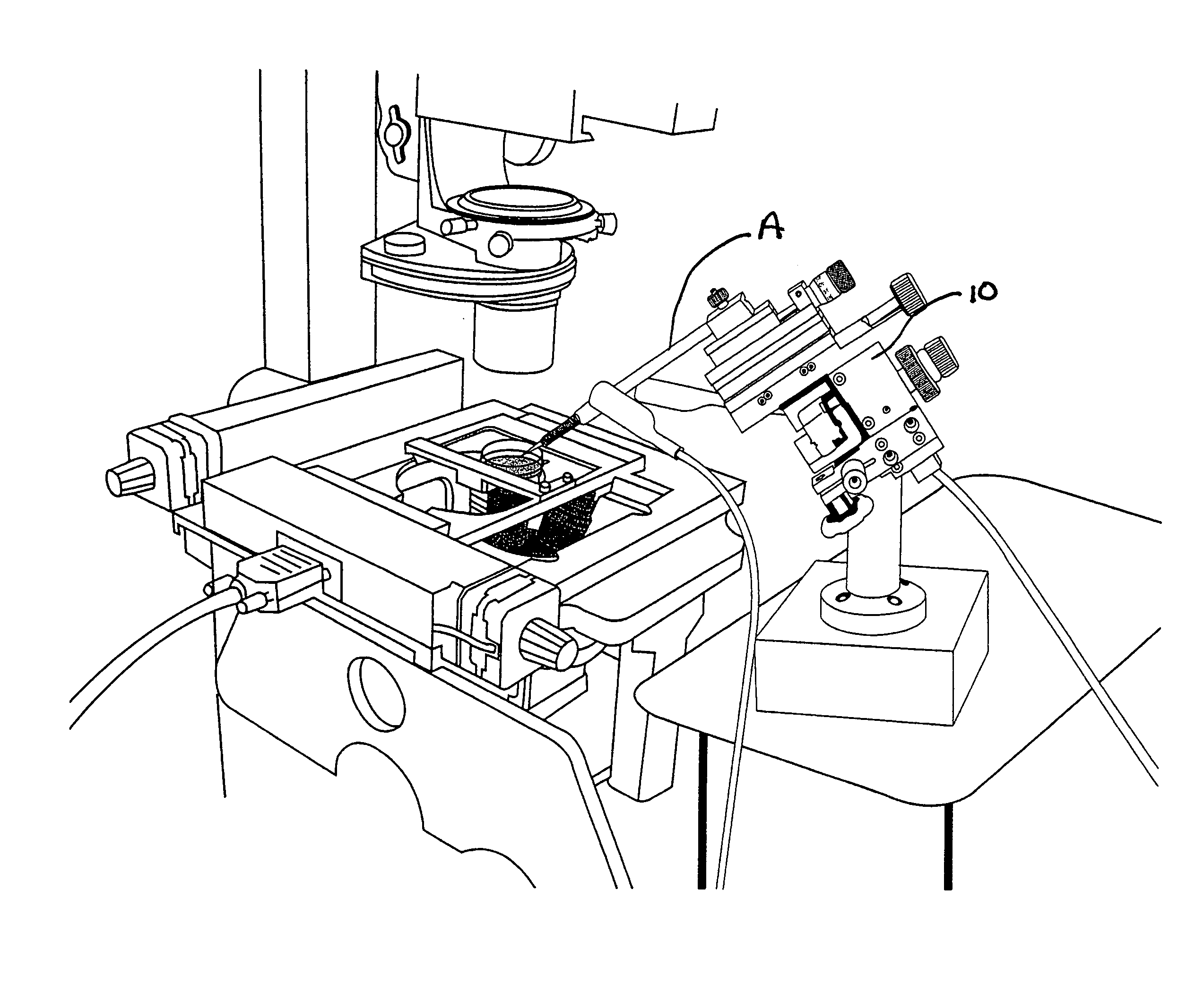
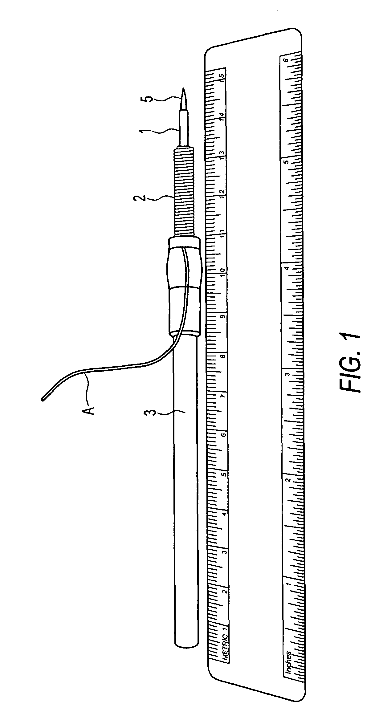
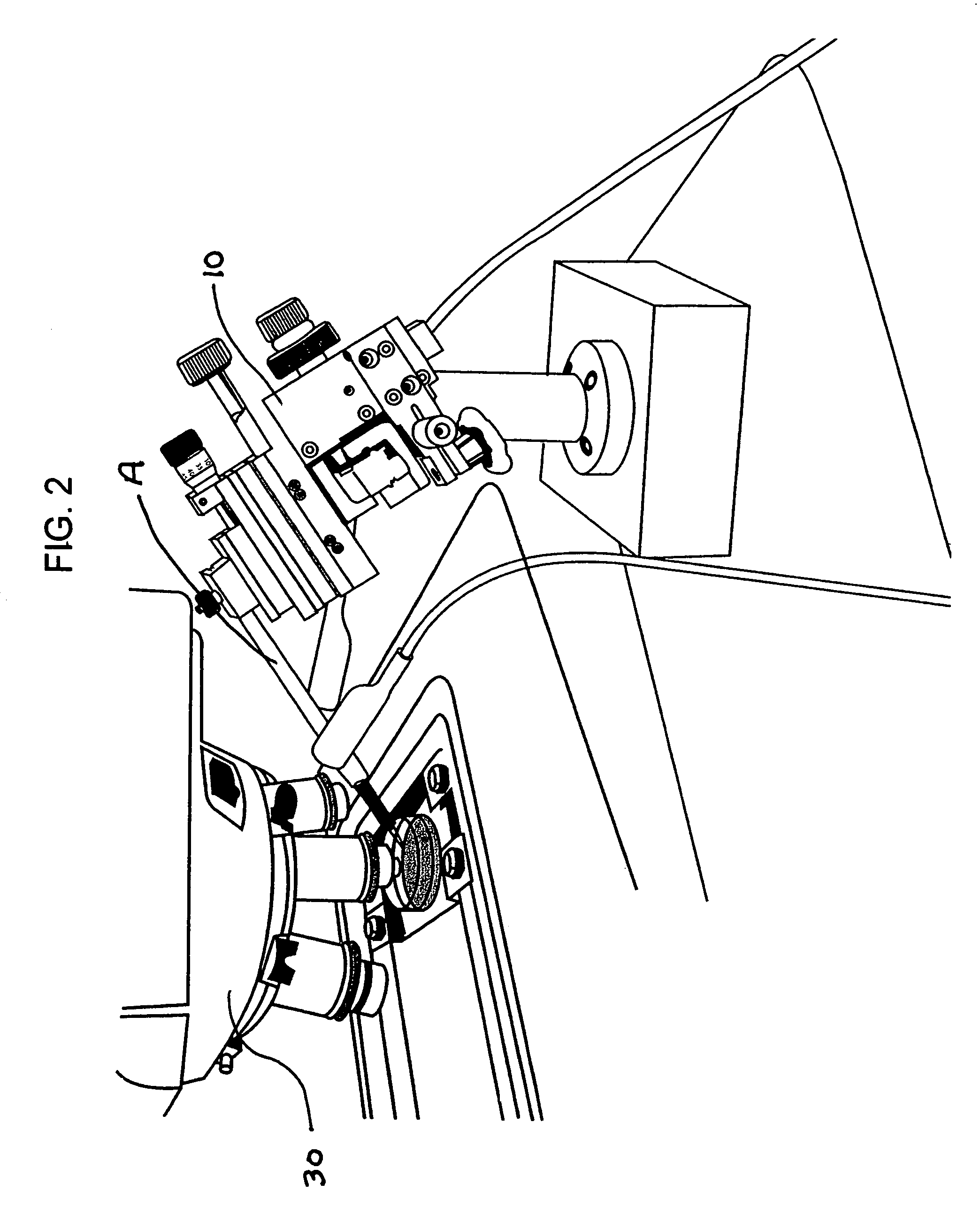
[0020]Shown in FIG. 1 is a prototype stylus style electromagnet probe suitable for use with a microscope, such as by attaching the probe to a micromanipulator. The probe A has a core 1, and conductive windings 2 surrounding the core 1. The windings are electrically connected to a DC power source. As shown, the core 2 is generally cylindrically shaped and has one end, the probe end 5, which is preferably pointed. The pointed probe end allows for accurate visualization of the placement of the electromagnetic probe and channeling of the magnetic field around the axis of the probe tip. In the prototype, the core was a steel dissection pin (about 1 / 16 inch in diameter) and the windings are copper wire. As shown in FIG. 1, the probe A includes cylindrical body 3 on which the core and windings are mounted to create a stylus electromagnetic probe. The prototype stylus probe is about six inches long, with a core diameter of about a sixteenth of an inch and the core / windings diameter of about...


PUM

PropertyMeasurementUnit
diameteraaaaaaaaaa
magnetic fieldaaaaaaaaaa
electromagneticaaaaaaaaaa

Abstract

The invention is an electromagnetic probe used in conjunction with a ferrofluid containng M particles. The electromagnetic probe is used to steer M-particles to a desired location, or use the M particles for mixing the ferrofluid. The probe can be used in conjunction with a microscope, a micromanipulator, a catheter or endoscope.

Description

FIELD OF INVENTION[0001]The invention relates to a portable electromagnetic probe that is used with ferrofluids in a in a variety of applications, including particle separation, particle placement and particle delivery, and particle mixing.BACKGROUND OF THE INVENTION[0002]Magnetic separation is a recent simple technique for isolation of cells, particles and organic molecules from complex mixtures by association, conjugating or labeling the molecule desired with a magnetic responsive material. The magnetic responsive material can be microbeads, such as the superparamagnetic beads available from Dynal Biotech as Dynabeads, magnetic nanoparticles, such as StemSep available from StemCell Technologies, and other magnetic particles or molecules that can be combined or attached to the cell or organic molecule of interest. Such magnetically “labeled” organic material is then positioned within a magnetic field to effect separation of the labeled material. The advantage of magnetic separation...

Claims


Application Information

Patent Timeline
Patent Type & Authority Patents(United States)
IPC IPC(8): B01D35/06G01N33/553
CPCB01F13/0809B01F15/00506B01F33/451B01F35/3202
Inventor DECOSTER, MARK A.BAZAN, NICOLAS G.
Owner BOARD OF SUPERVISORS OF LOUISIANA STATE UNIV & AGRI & MECHANICAL COLLEGE
Learn More