Optical disc

a technology of optical discs and auxiliary information, applied in the field of optical disc structure, can solve the problems of unable to read and the identifying information recorded in the auxiliary information recording area (bca) dc may not function as a copy protection key with reliability,

Active Publication Date: 2010-08-03
PIONEER CORP
View PDF9 Cites 0 Cited by
  • Summary
  • Abstract
  • Description
  • Claims
  • Application Information

AI Technical Summary

Benefits of technology

[0022]In the optical disc according to the embodiment, the depth of, for example, a track groove or a prepit formed in an auxiliary information recording area is smaller than that a track groove or a prepit formed in a main information recording area. Alternatively, a track groove or a prepit is not formed in the auxiliary information recording area. Thereby, the effects of, for example, interference from the grooves and lands in the auxiliary information recording area on a reproduced RF signal when tracking is open are reduced or eliminated. This makes it possible to reliably read identifying information recorded in the auxiliary information recording area (BCA) D1C.
[0025]In the above embodiment, further, when a wavelength 660 nm of a laser beam is used for recording / reproducing an optical disc such as for DVD, the depth of each of the grooves or prepits formed in the recording layer of the auxiliary information recording area is set at less than 65 nm. Thereby, reliable reading of the identifying information recorded in the auxiliary information recording area is made possible.
[0026]In the above embodiment, further, when a wavelength 405 nm of a laser beam is used for recording / reproducing an optical disc such as for BD, the depth of each of the grooves or prepits formed in the recording layer of the auxiliary information recording area is set at less than 40 nm. Thereby, reliable reading of the identifying information recorded in the auxiliary information recording area is made possible.

Problems solved by technology

As a result, the reading of the identifying information recorded in the auxiliary information recording area (BCA) DC may be made impossible.
In this event, the identifying information recorded in the auxiliary information recording area (BCA) DC may possibly fail to function as a copy protect key with reliability.

Method used


Image

  • Optical disc
  • Optical disc
  • Optical disc

Examples


Embodiment Construction

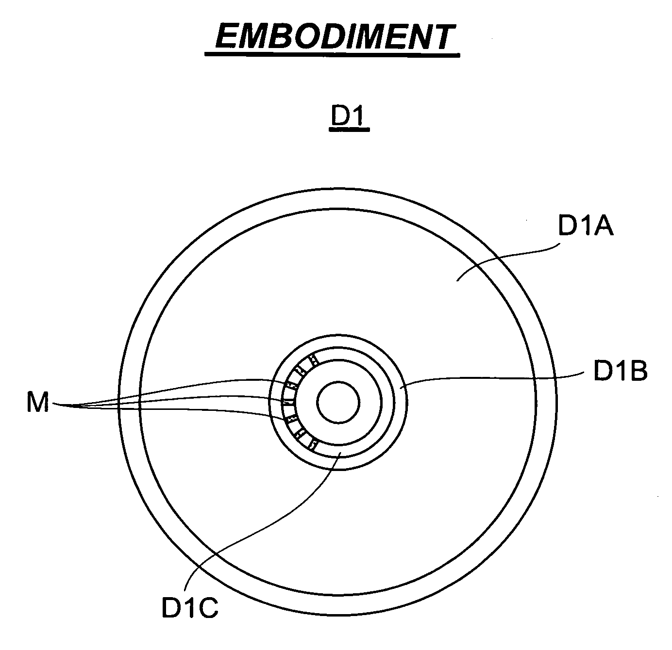
[0036]FIGS. 4 and 5 illustrate an embodiment of an optical disc according to the present invention. FIG. 4 is a plan view of the record surface of the optical disc in the embodiment. FIG. 5 is an enlarged view of a part of the record surface of an auxiliary information recording area (BCA) in the embodiment.

[0037]In FIG. 4, the optical disc D1 has, as in the case of the conventional optical disc, a record surface containing a main information recording area D1A, a control information recording area D1B provided next to the inner peripheral end of the main information recording area D1A, and an auxiliary information recording area (BCA) D1C provided next to the inner peripheral end of the control information recording area D1B.

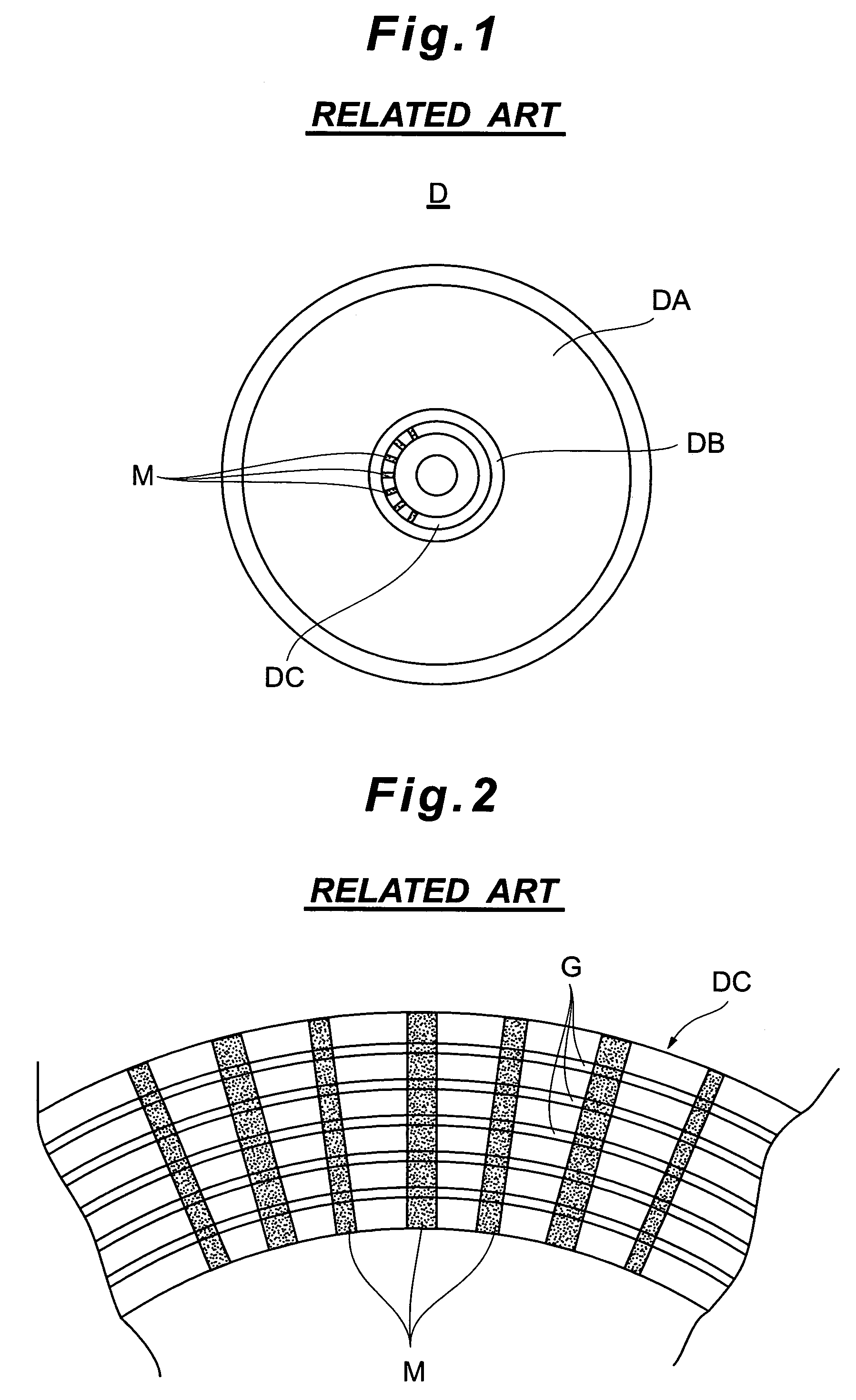
[0038]In the auxiliary information recording area D1C, as shown in FIG. 5, marks M are written in barcode form for identifying information such as an ID number for identifying the individual optical discs D1, at the factory prior to shipment, as in the case of ...


PUM

PropertyMeasurementUnit
depthaaaaaaaaaa
depthaaaaaaaaaa
depthaaaaaaaaaa

Abstract

A recording layer close to a disc surface is divided into at least two recording areas, a main information recording area D1A and an auxiliary information area (BCA) D1C. Grooves are formed in the main information recording area D1A. Marks M are formed in barcode form representing identifying information in the auxiliary information recording area (BCA) D1C. Track grooves G1 or prepits are formed in the recording layer of the auxiliary information recording area (BCA) D1C and have a depth smaller than that of the groove formed in the main information recording area D1A.

Description

BACKGROUND OF THE INVENTION[0001]1. Field of the Invention[0002]This invention relates to the structure of an optical disc having an auxiliary information recording area.[0003]The present application claims priority from Japanese Application No. 2005-295203, the disclosure of which is incorporated herein by reference.[0004]2. Description of the Related Art[0005]FIG. 1 illustrates the structure of a conventional optical disc containing an auxiliary information recording area, such as DVD.[0006]The optical disc D shown in FIG. 1 has a record surface containing a main information recording area DA, a control information recording area DB provided next to the inner peripheral end of the main information recording area DA, and an auxiliary information recording area DC provided next to the inner peripheral end of the control information recording area DB.[0007]In the auxiliary information recording area DC which is what is called BCA (Burst Cutting Area), marks M are written in barcode f...

Claims


Application Information

Patent Timeline
Patent Type & Authority Patents(United States)
IPC IPC(8): G11B7/24G11B7/24079G11B7/24094G11B7/24097
CPCG11B7/00736G11B7/24079G11B20/00086G11B20/00115G11B20/00268G11B2220/2541G11B2220/2562
Inventor OSHIMA, SEIROTAKISHITA, TOSHIHIKOMURAMATSU, EIJINISHIWAKI, HIROSHI
Owner PIONEER CORP
Why Eureka
Try Eureka