
Method and apparatus for improving the reliability of the reading of integrated circuit fuses

Inactive Publication Date: 2005-06-07
SEMTECH CORP
View PDF7 Cites 7 Cited by
  • Summary
  • Abstract
  • Description
  • Claims
  • Application Information

AI Technical Summary

Benefits of technology

[0012]It would be advantageous if an approach could be developed which permits determining, before a chip is placed into service, whether the chip is likely to provide a reliable reading of its fuses. If s

Problems solved by technology

But in recent times there has been great pressure on system designers to reduce the size and power consumption of a system.
In such a system, any decision that adds to the bulk or weight is undesirable, for example a decision to increase the chip count (to accommodate an external memory) or a decision to add a backup battery for a memory.
While Ti-silicide doping has the advantage of reducing the unblown resistance and resisting explosive decomposition, it has a potential drawback in that it “blowing” such a fuse results only in a process of silicide agglomeration once the fuse heats up to around 800° C. This results in the fuse undergoing a phase change of state which results in the fuse impedance changing from its unblown state of around 100 ohms to its blown state of any value from around 1 KΩ to 500 KΩ.
This means that it is not easy to know exactly what resistance in the fuse represents a “blown” state.
Experience shows that such a blown fuse may change its resistance slightly with temperature or aging.
Such a result is extremely undesirable.

Method used


Image

  • Method and apparatus for improving the reliability of the reading of integrated circuit fuses
  • Method and apparatus for improving the reliability of the reading of integrated circuit fuses

Examples


first embodiment

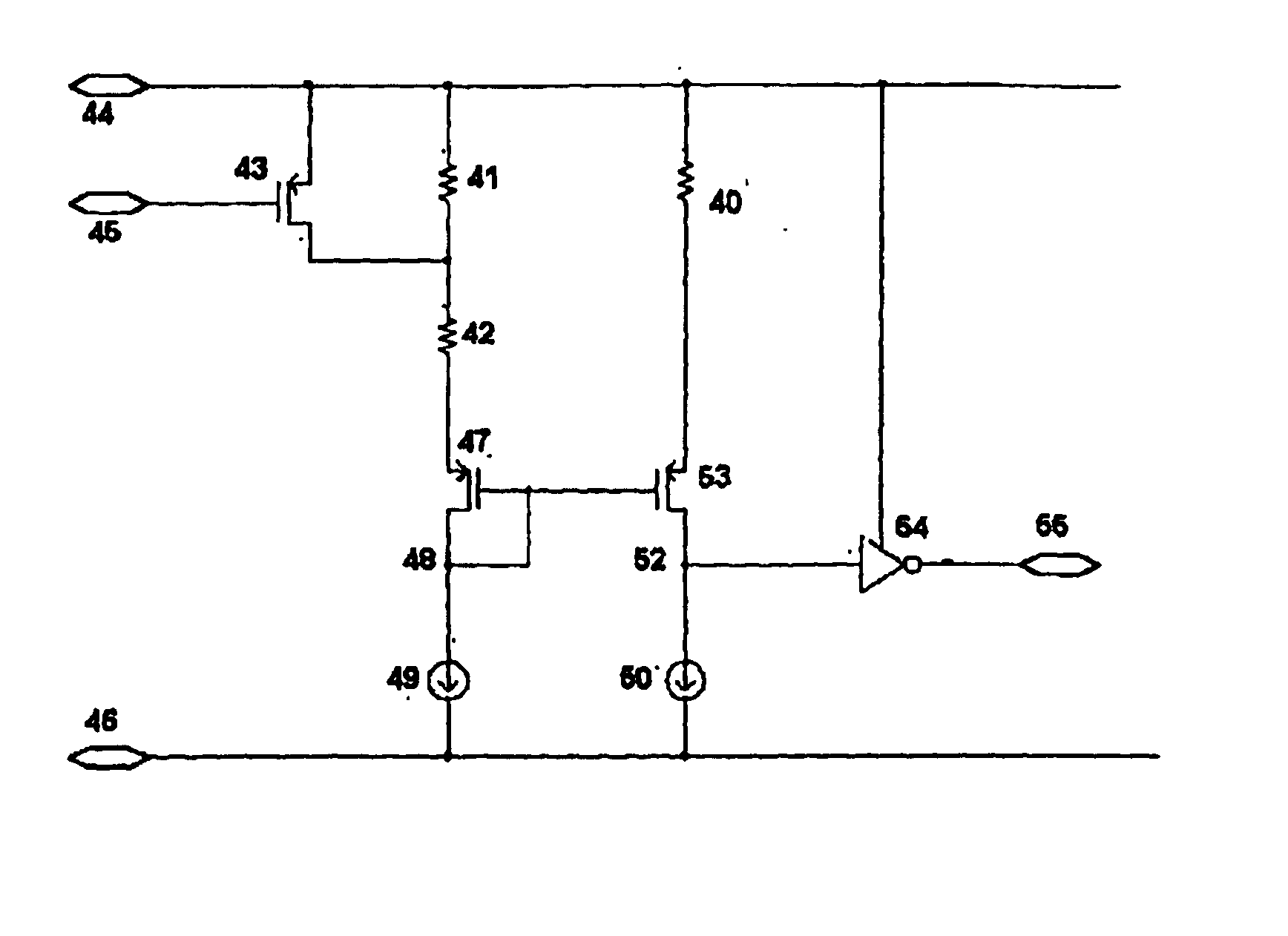
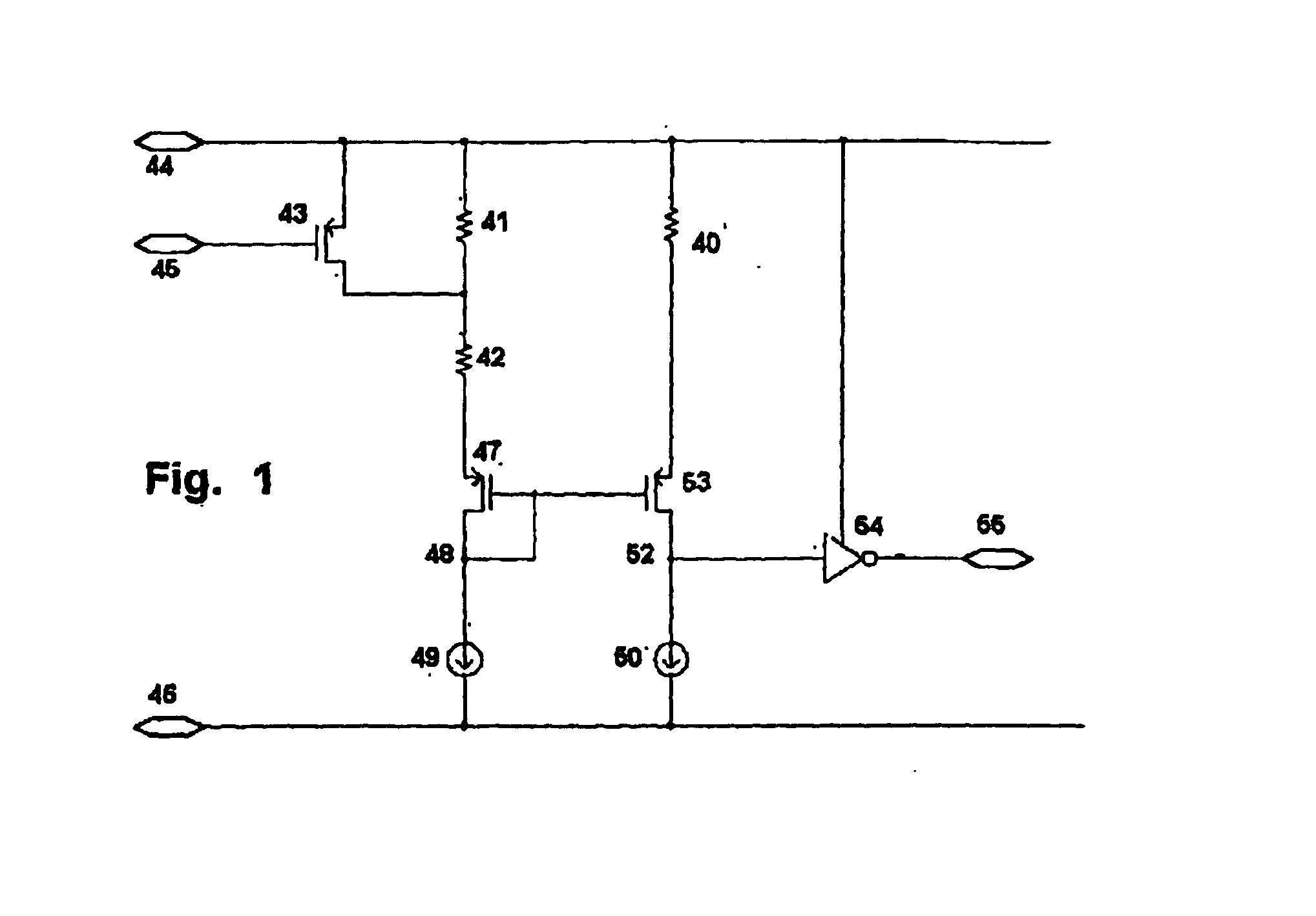
[0030]In a first embodiment, a first constant-current reference 49 is connected in series with first and second resistors 42, 41 with a first MOSFET transistor 47 with source and drain between the first constant-current reference 49 and the first and second resistors 42, 41, a connection between the first constant-current reference 49 and the first MOSFET transistor 47 defining a first node 48. In addition, a second constant-current reference 50 is connected in series with the fuse 40 with a second MOSFET transistor 53 with source and drain between the second constant-current reference 50 and the fuse 40, a connection between the second constant-current reference 50 and the second MOSFET transistor 53 defining a second node 52. A switch 43 is in parallel with the second resistor 41. The gates of the first and second MOSFET transistors 47, 53 are connected together and to the first node 48. In this embodiment the first resistor 42 defines the first reference resistance, and the serie...

second embodiment

[0031]In a second embodiment, the series-wise combination of the first and second resistors is connected to the negative supply voltage, and the is fuse also connected to the negative supply voltage. The first constant-current reference is a current source also connected to the positive supply voltage. The second constant-current reference is a current source also connected to the positive supply voltage. The MOSFET transistors are NMOS.

third embodiment

[0032]In a third embodiment, a first constant-current reference is connected in series with the first and second resistors, and a connection between the first constant-current reference and the first and second resistors defines a first node. A second constant-current reference is connected in series with the fuse, and a connection between the second constant-current reference and the fuse defines a second node. The first resistor defines the first reference resistance, and the series-wise combination of the first and second resistors defining the second reference resistance. A comparator receiving as inputs signals from the first and second nodes, and its output defines an output of the apparatus.


PUM


Abstract

A system is provided for use with an on-chip fuse. If the fuse (40) is to be blown, the system blows the fuse, then performs a test read by comparing it with a larger-than-normal reference resistance (41, 42). If, even using the larger-than-normal reference resistance, the fuse reads as blown, then it is possible to be much more confident that the fuse will read correctly when compared against the normal reference resistance (42), even with aging and with variations of temperature and supply. For future reads during normal operation, the system compares it with the normal reference resistance (42). If, on the other hand, the fuse does not read as blown during the test read then the device can be rejected as a failed device.

Description

[0001]This application claims priority from U.S. appl. No. 60 / 379,377 entitled “Method for improving the reliability of integrated circuit fuse reading” and filed May 8, 2002, which application is incorporated herein by reference.BACKGROUND[0002]The application relates generally to blowing and reading fuses formed within integrated circuits, and relates particularly to reading the fuses in a way that has improved reliability.[0003]In many systems it is desirable to have a nonvolatile memory. In some applications a static RAM with a backup battery will be suitable, and in other applications an EEPROM may be suitable. But in recent times there has been great pressure on system designers to reduce the size and power consumption of a system. Such pressure is particularly great with cellular telephones, personal digital assistants (PDAs), and notebook computers. In such a system, any decision that adds to the bulk or weight is undesirable, for example a decision to increase the chip coun...

Claims


Application Information

Patent Timeline
IPC IPC(8): G11C17/14G11C17/18G11C17/16G11C29/02G01R31/74
CPCG11C17/16G11C29/027G11C29/02G11C17/18G01R31/07G01R31/74
Inventor HEJDEMAN, CARL R. M.MCKNIGHT, ANDREW
Owner SEMTECH CORP
Learn More