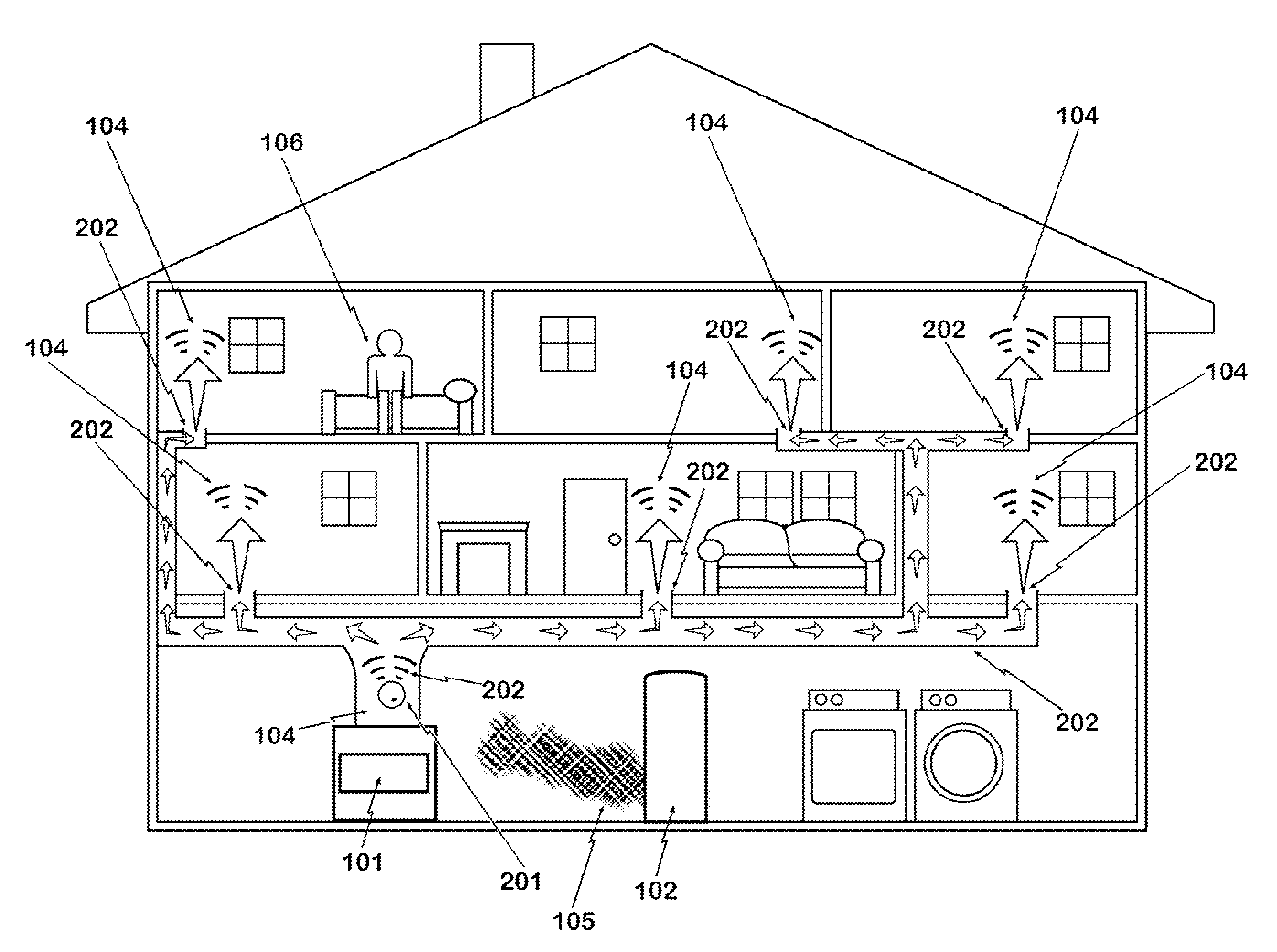
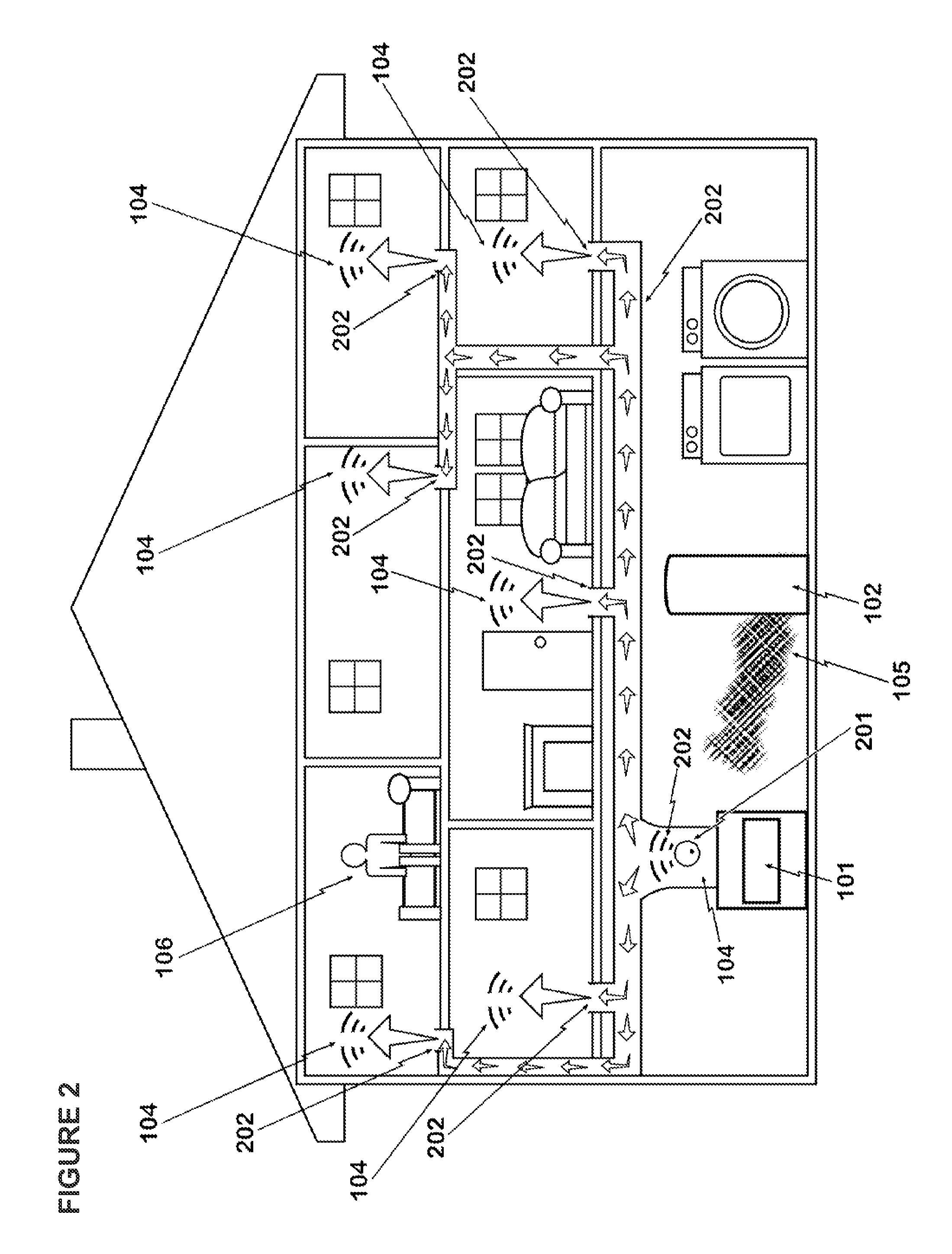
Use of heating and/or ventilation ductwork to broadcast alarm conditions
a technology of heating and ventilation ductwork and broadcasting alarm conditions, which is applied in the direction of fire alarm smoke/gas actuation, signalling system, hydrostatic/pneumatic audible signalling, etc., and can solve the problems of adding a lot to the cost and the need for maintenan
- Summary
- Abstract
- Description
- Claims
- Application Information
AI Technical Summary
Benefits of technology
Problems solved by technology
Method used
Image

Examples
example 1
[0030]A short tube 304 is attached to the sound source 303. This tube 304 is inserted or plugged into a hole drilled into existing ductwork 202 of a heating or air conditioning system. (FIG. 3)
example 2
[0031]The sound source 403 is removed from a typical alarm device 401, 402, 403 and replaced with a short post 404. The sound source 403 is then attached to the end of this post 404. The post 404 and sound source 403 are then inserted into the ductwork 202, through a hole of appropriate size. (FIG. 4)
example 3
[0032]A sound source 503 is attached on the outside of existing ductwork 202, so that the audible alarm signal is fed through the wall of the duct 202. (FIG. 5)
PUM
 Abstract
Description
Claims
Application Information
 - R&D
- Intellectual Property
- Life Sciences
- Materials
- Tech Scout
- Unparalleled Data Quality
- Higher Quality Content
- 60% Fewer Hallucinations
Browse by: Latest US Patents, China's latest patents, Technical Efficacy Thesaurus, Application Domain, Technology Topic, Popular Technical Reports.
© 2025 PatSnap. All rights reserved.Legal|Privacy policy|Modern Slavery Act Transparency Statement|Sitemap|About US| Contact US: help@patsnap.com