Method and apparatus for phase change enhancement

a phase change and enhancement technology, applied in the direction of steam generation using hot heat carriers, distillation in pipe stills, liquid fuel engine components, etc., can solve the problems of difficult to achieve accurate level control in a portable system, apparatus can easily clog, thin and more rapid moving liquid film

a phase change and enhancement technology, applied in the direction of steam generation using hot heat carriers, distillation in pipe stills, liquid fuel engine components, etc., can solve the problems of difficult to achieve accurate level control in a portable system, apparatus can easily clog, thin and more rapid moving liquid film

US7785448B2Active Publication Date: 2010-08-31DEKA PROD LLP

Image

  • Method and apparatus for phase change enhancement
  • Method and apparatus for phase change enhancement
  • Method and apparatus for phase change enhancement

Examples


Embodiment Construction

[0021]Various embodiments of the present invention are directed to techniques for enhancing the efficiency of phase change for liquids, such as in an evaporator. As used in this application, the term “boiling” will be understood to include a phase change between liquid and vapor where no bubbles are formed, as well as a phase change where bubbles are formed.

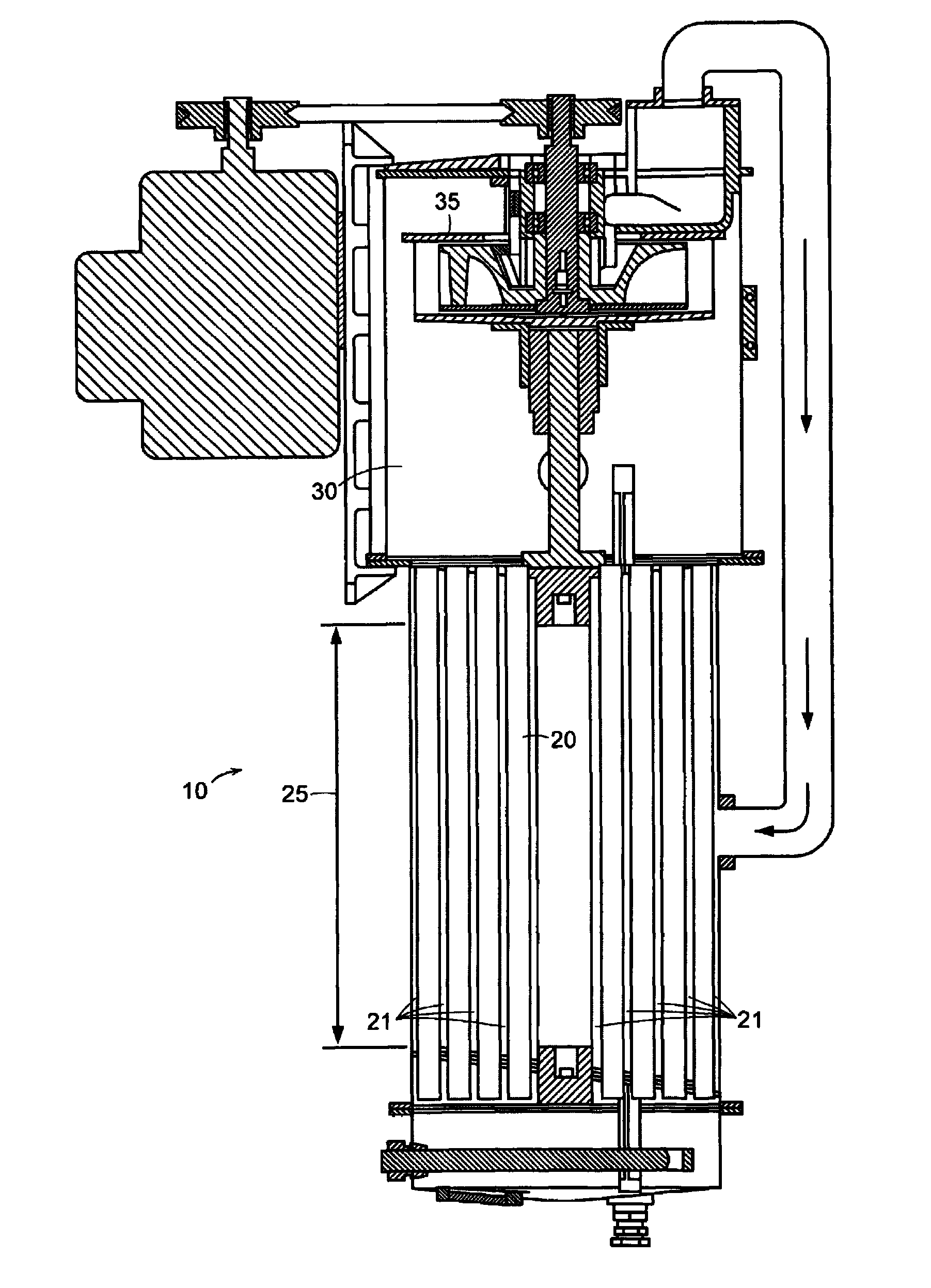
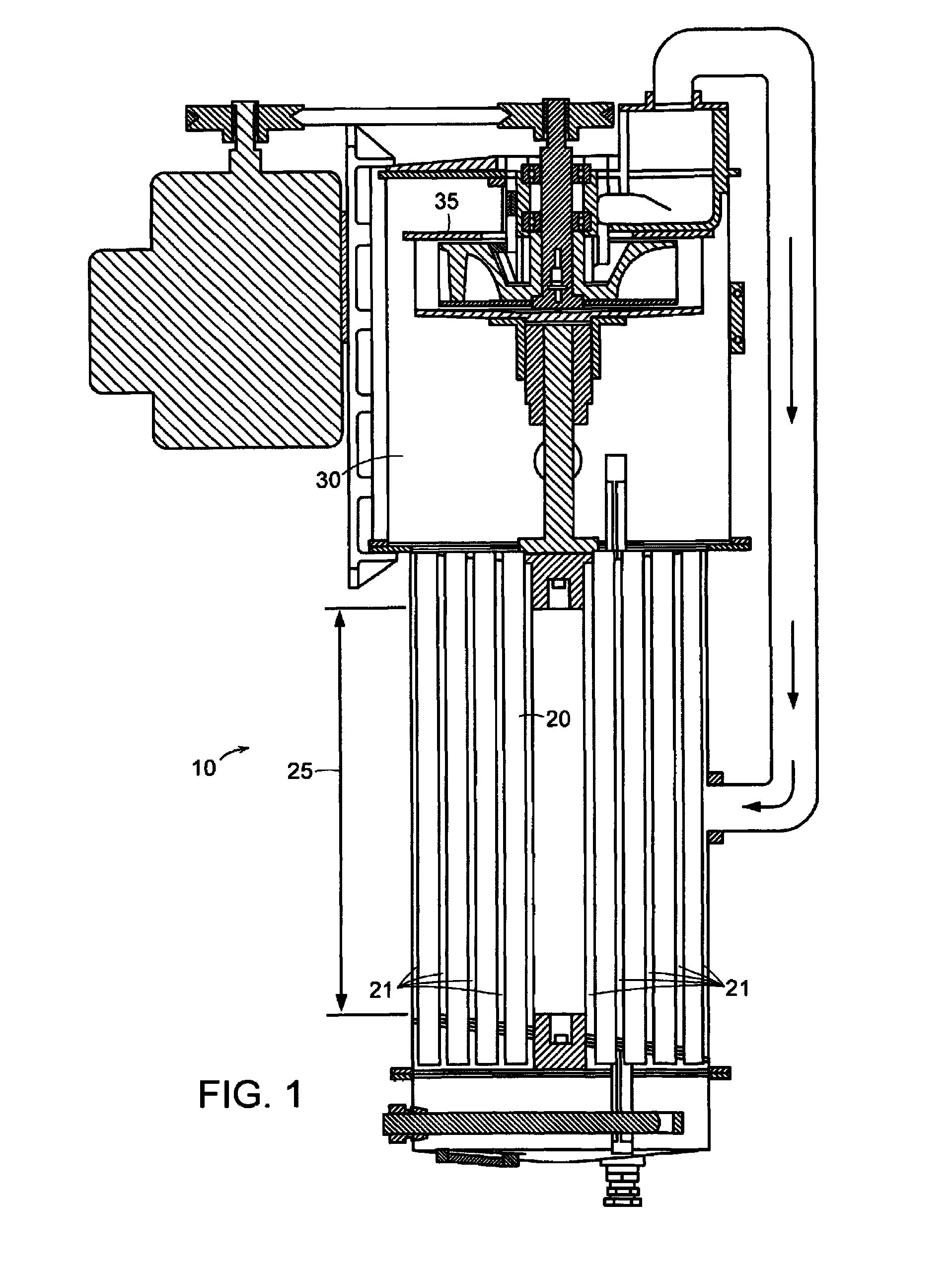
[0022]FIG. 1 shows an evaporator 10 for distilling a liquid according to an embodiment of the present invention. The evaporator includes a set 20 of cylindrical evaporator tubes 21 that are substantially vertically oriented. Liquid is introduced to each tube through an inlet at the bottom of each tube. Each tube includes a heated central region 25 for boiling the liquid and producing vapor. Each tube has a vent opening that allows vapor to escape from the tube into an evaporation chamber 30. Liquid that has not undergone phase change also escapes through the vent opening into the chamber where the liquid may be recirculated to th...


PUM

PropertyMeasurementUnit
diameteraaaaaaaaaa
diametersaaaaaaaaaa
diametersaaaaaaaaaa

Abstract

A method of operating an evaporator is described. In evaporator feed water, a Taylor bubble is developed which has an outer surface including a thin film in contact with an inner surface of an outer wall of an evaporator tube. The Taylor bubble is heated as it rises within the evaporator tube so that liquid in the thin film transitions into vapor within the bubble.

Description

[0001]The present application claims priority from United States Publication No. US-2004-0074757-A1, published Apr. 22, 2004 and entitled Method and Apparatus for Phase Change Enhancement, now abandoned, which in turn claimed priority from U.S. provisional patent application Ser. No. 60 / 401,813, filed Aug. 7, 2002, entitled “Method and Apparatus for Boiling Enhancement in a Rising Film Evaporator,” and from U.S. provisional patent application Ser. No. 60 / 425, 820, filed Nov. 13, 2002, entitled “Pressurized Vapor Cycle Liquid Distillation.” Each of these applications is incorporated herein by reference in its entirety.FIELD OF THE INVENTION[0002]The present invention pertains to improvements for the conversion of liquid to vapor, such as the phase change that takes place in an evaporator.BACKGROUND ART[0003]The conversion of liquid to vapor is a fundamental step in many processes. For a variety of reasons, such as time and energy limitations, it may be advantageous to make this phase...

Claims


Application Information

Patent Timeline
31 Aug 2010
Publication
US7785448B2
IPC
B01D1/06; B01D1/22; B01D3/04; B01D3/28; C02F1/08; C02F1/16; B01D1/28; B01D3/10; B01D3/42; B01D5/00; B01D29/01; B01D35/12; F04C19/00; F04C29/00; F28D7/00; F28D7/16; F28D9/00; F28F1/40; F28F13/00
CPC
B01D1/06; B01D1/221; B01D1/28; B01D1/2887; B01D1/289; B01D1/2893; B01D3/42; B01D5/0015
Inventors
OWENS, KINGSTON