
Roof support apparatus for solar panels

a technology for solar panels and support devices, applied in the direction of solar thermal energy generation, solar heating energy, ceilings, etc., can solve the problems of insufficient rigidity, lateral or upward force, and insufficient support of current support devices

Active Publication Date: 2010-09-21
TESLA INC
View PDF26 Cites 52 Cited by
  • Summary
  • Abstract
  • Description
  • Claims
  • Application Information

AI Technical Summary

Benefits of technology

The present invention is a roof support apparatus that can be used to secure a load to a roof that is covered with tiles. It consists of a mounting plate, attachment members, and an upper support member. The mounting plate is placed on the roof and has a narrow track parallel to the base. The attachment members extend through the roof's base and are positioned on either side of the track. The upper support member passes through the roof covering material and engages with a screw that can slide along a tack until it is fully engaged. This invention provides a simple and effective way to secure loads to roofs with tiled coverings.

Problems solved by technology

These loads may also experience lateral or upward forces which may be caused by large gusts of wind.
Attaching support for tile roofs presents a special problem due to their uneven surfaces and the ceramic and cement material of the tiles which may be brittle.
Current support apparatus do not provide adequate support for lateral forces or forces perpendicular to the plane of the roof deck on the supports and may not be rigid enough to prevent movement of the supports.
Forces in parallel with the roof line may create pressure on the tiles and may cause cracking of the tiles and subsequent leaks around the area of the support members.
Additionally, the loads that require support can be very large.
However, such beams typically do not align with the tiles in a way that is conducive for effective mounting.

Method used


Image

  • Roof support apparatus for solar panels
  • Roof support apparatus for solar panels
  • Roof support apparatus for solar panels

Examples


Embodiment Construction

[0019]Described herein are techniques for roof support apparatus, which may be used for solar panels for example. In the following description, for purposes of explanation, numerous examples and specific details are set forth in order to provide a thorough understanding of the present invention. It will be evident, however, to one skilled in the art that the present invention as defined by the claims may include some or all of the features in these examples alone or in combination with other features described below, and may further include modifications and equivalents of the features and concepts described herein.

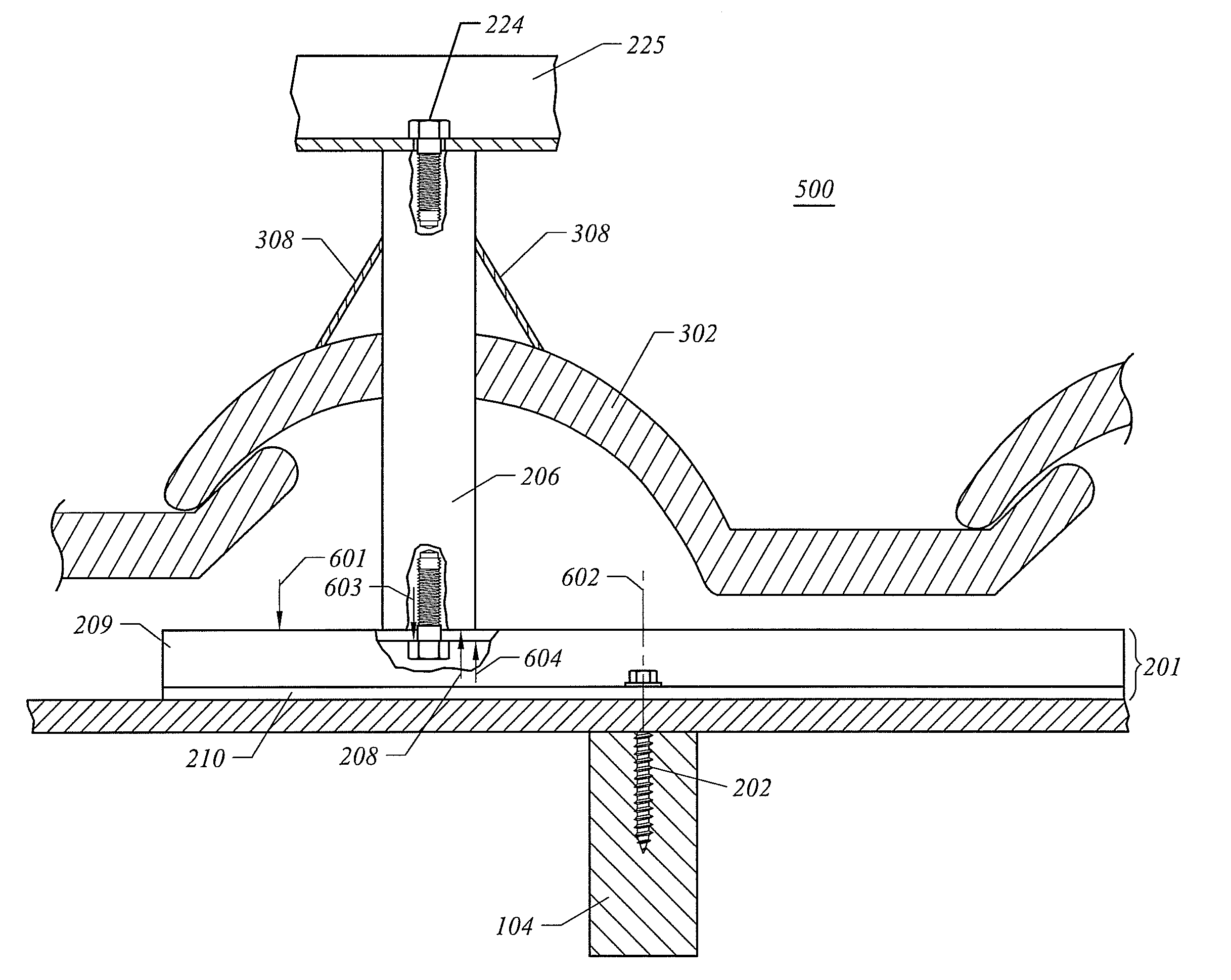
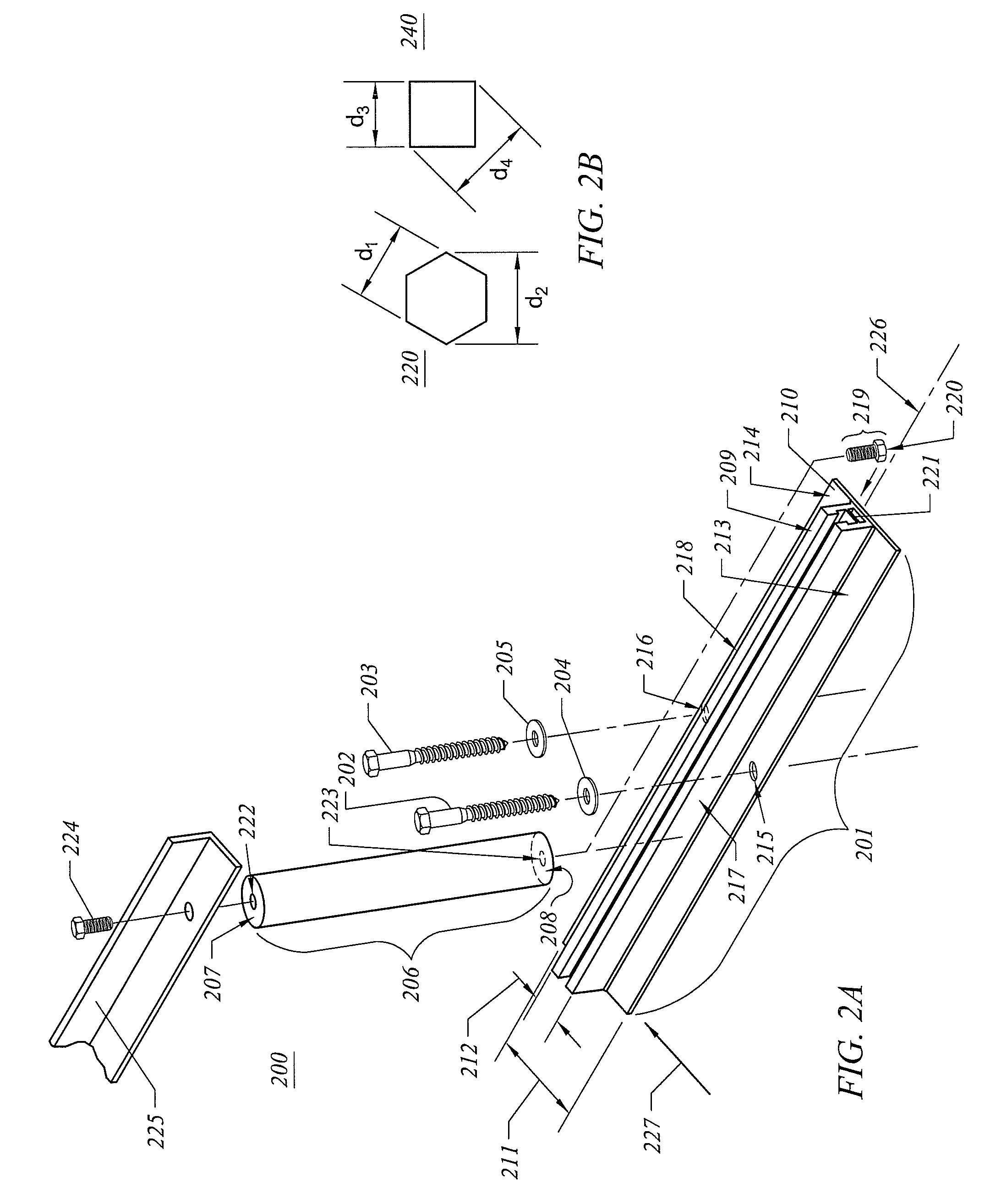
[0020]FIG. 2A illustrates an exploded view of a roof support apparatus 200 according to one embodiment of the present invention. Roof support apparatus 200 includes mounting plate 201, an upper support member 206, an attachment member 202, an attachment member 203, a screw 219, and two washers (204 and 205). Roof support apparatus 200 provides adjustment of the support wh...


PUM


Abstract

In one embodiment, the present invention includes a roof support apparatus which may be used for securing a load to a tile-covered roof. The roof support apparatus comprises a mounting plate, a first and second attachment member, an upper support member, and a load. The mounting plate engages its base with an upper surface of the roof. A track of the mounting plate extends parallel to the base and has a width less than a width of said base. The first and second attachment members are adapted to extend downward through an exposed surface of the base on both sides of the track. The upper support member is adapted to pass vertically upward through an opening in a roof covering material, such as tile, and engage a screw which may slide along the tack until the screw and the upper support member are fully engaged.

Description

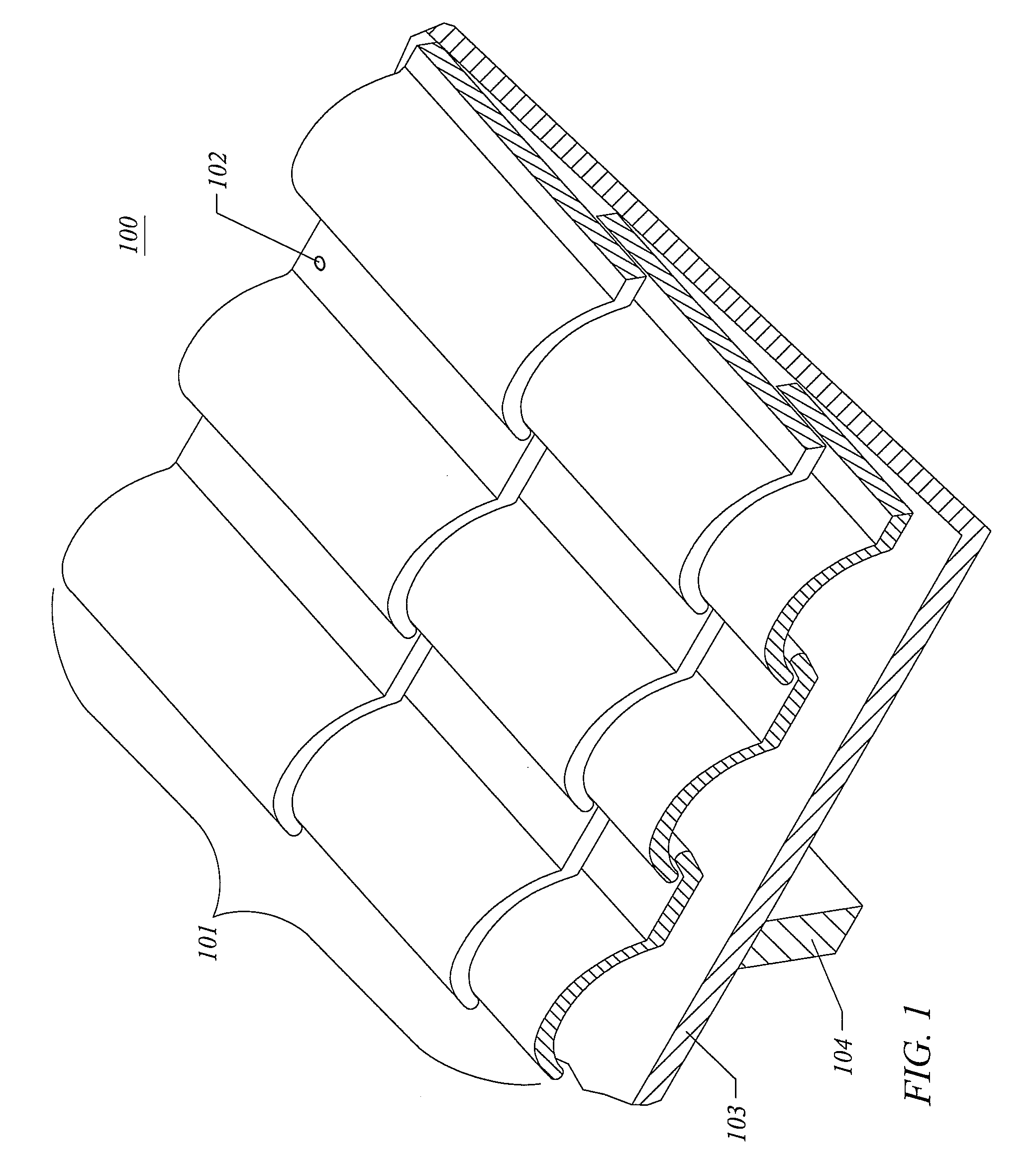
CROSS REFERENCE TO RELATED APPLICATIONS[0001]Not ApplicableBACKGROUND[0002]The present invention relates to roof support, and in particular, to tile roof support apparatus for solar panels.[0003]Satellite dishes and solar panels are often supported upon a roof. These loads stand off from the roof shingles and require support for their weight. These loads may also experience lateral or upward forces which may be caused by large gusts of wind.[0004]Attaching support for tile roofs presents a special problem due to their uneven surfaces and the ceramic and cement material of the tiles which may be brittle. In this case, the roof supports cannot be attached on top of the tile roof. Roof rafters and under-lying decking (like plywood or planking) typically provide the support required to mount loads such as satellite dishes and solar panels to tile roofs. FIG. 1 illustrates an example of a tile roof 100 which may require a mounting of a load.[0005]Tile roof 100 includes rows of adjacent t...

Claims


Application Information

Patent Timeline
Patent Type & Authority Patents(United States)
IPC IPC(8): E04H14/00
CPCF24J2/5205F24J2/5245F24J2/5249F24J2/526H01Q1/1207H01Q1/1242Y02B10/20Y02E10/47F24S25/615F24S25/61F24S25/33F24S25/65
Inventor TARBELL, BENCONCHO, CHRISTINEJENSEN, SORENARDELL-SMITH, ZACK
Owner TESLA INC
Learn More