Method and apparatus for testing composite materials

a composite material and test method technology, applied in the direction of measuring devices, scientific instruments, instruments, etc., can solve the problems of low apparent through-thickness tensile strength, inability to extract coupons directly, and inability to generate true through-thickness tensile strength data for materials containing reinforcement in more than one direction

Inactive Publication Date: 2010-09-21
AIRBUS OPERATIONS LTD
View PDF15 Cites 12 Cited by
  • Summary
  • Abstract
  • Description
  • Claims
  • Application Information

AI Technical Summary

Problems solved by technology

Disadvantages of this method include a significant sensitivity to flaws and variations in the test material, the results may be influenced by interaction between interlaminar shear stresses and through-thickness tensile stresses, giving a low apparent through-thickness tensile strength result, the test coupons must be manufactured to a dedicated L-shaped geometry, which means that in most cases the coupons cannot be extracted directly from candidate materials, and this method does not allow true through-thickness tensile strength data to be generated for materials containing reinforcement in more than one direction, such as FRPs containing woven fabric.
Disadvantages of this method include the results are dependent on obtaining a good bond between the coupon and the end blocks and are very sensitive to alignment of the end blocks during bonding and the alignment of the grips of the apparatus used to apply the load (load frame).
The bonding of the end blocks to some materials, for example thermoplastics, can be difficult and can result in premature coupon failure.

Method used


Image

  • Method and apparatus for testing composite materials
  • Method and apparatus for testing composite materials
  • Method and apparatus for testing composite materials

Examples


Embodiment Construction

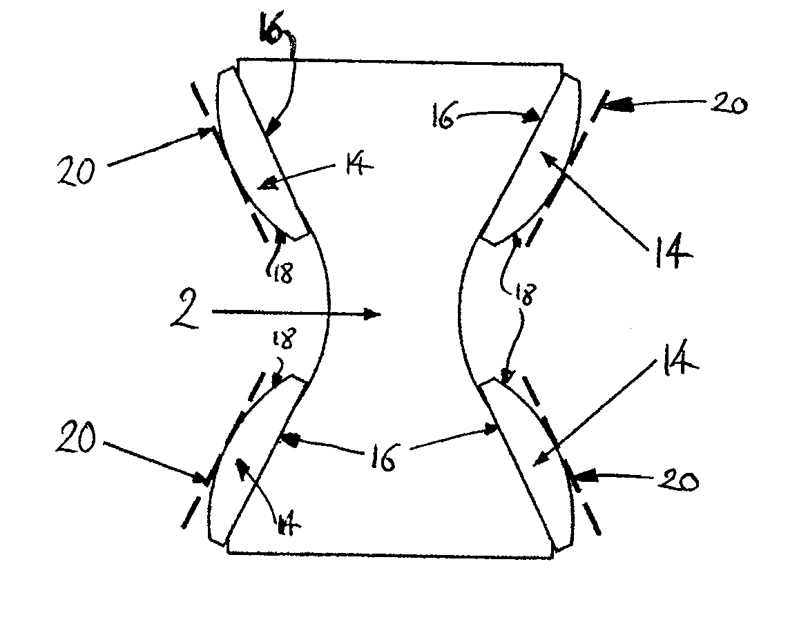
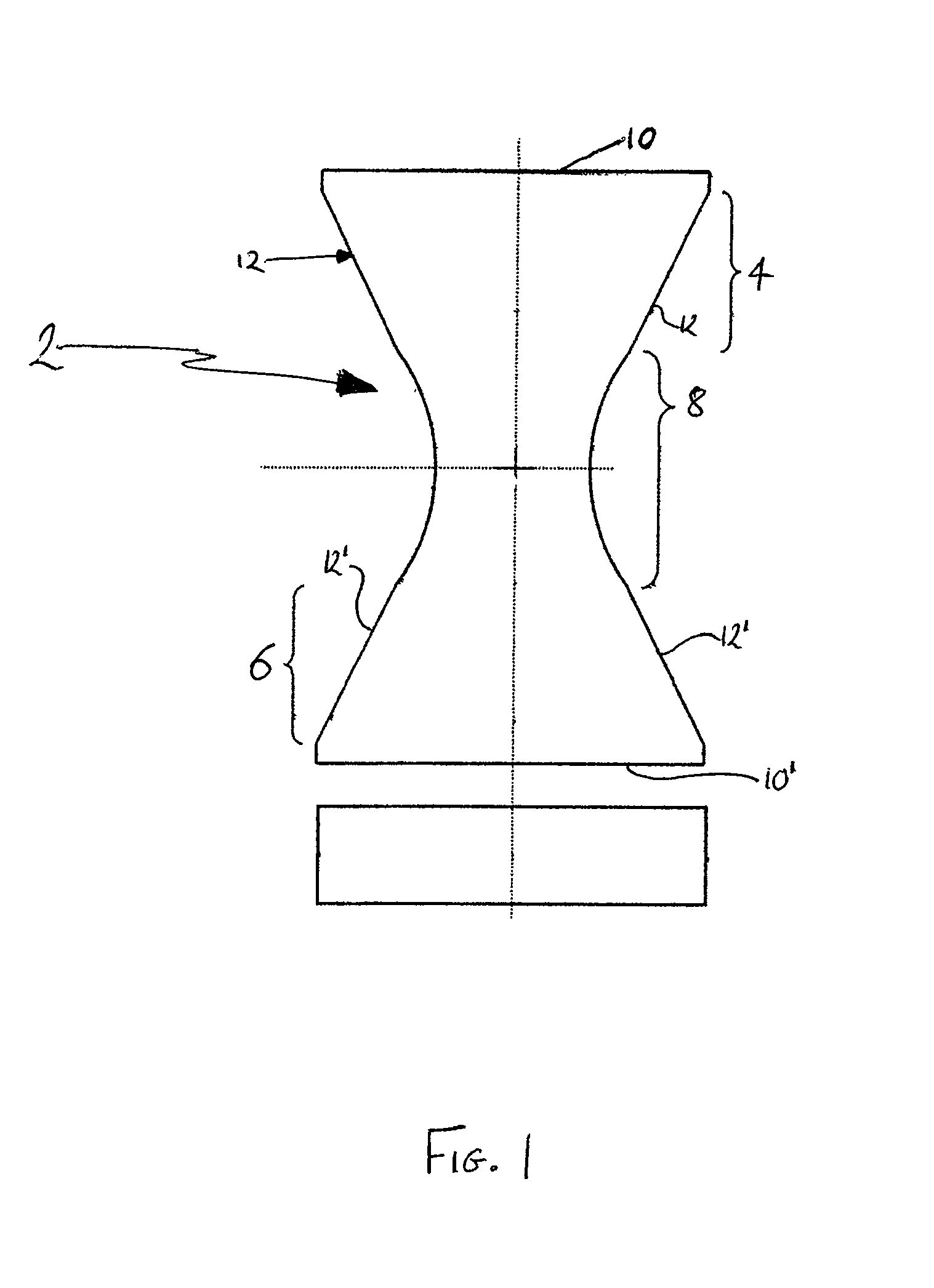
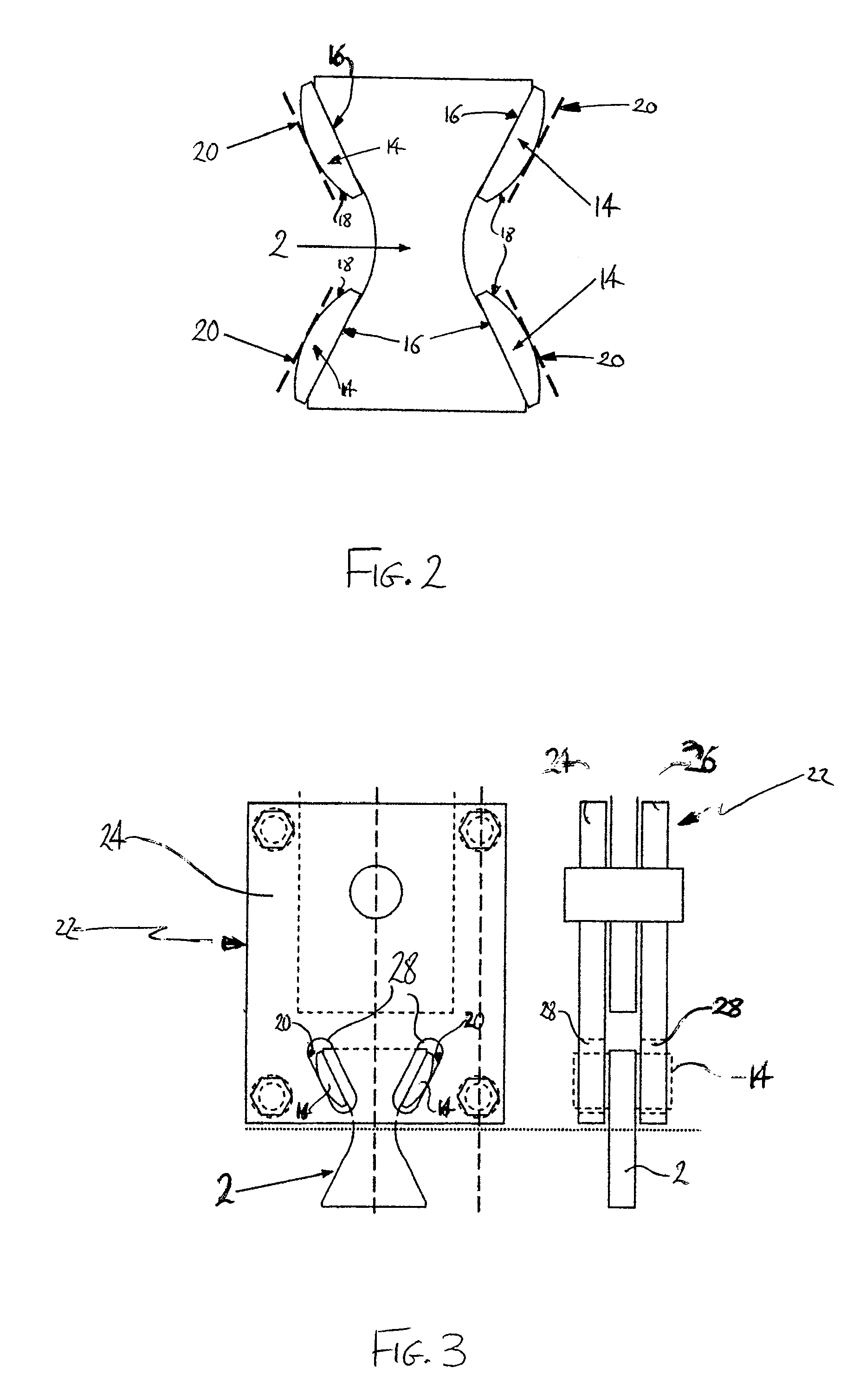
[0024]FIG. 1 illustrates a front and top elevation of a test coupon according to an embodiment of the present invention. The front elevation shows a two-dimensional ‘hourglass’ shape, with the coupon having a constant thickness, as indicated by the rectangular top elevation. The coupon 2 comprises generally of three regions; first and second load introduction regions 4,6 at either end of the coupon and a gauge section 8 adjoining each load introduction region. Each of the first and second load introductions regions 4,6 have a generally trapezoidal shape orientated such that the longer of the parallel sides 10, 10′ form the ends of the coupon and the shorter of the parallel sides adjoining the gauge section 8. The angled sides 12, 12′ of each load introduction region form the load introduction surfaces to which the test loads are applied. As will be explained further below, the load introduction surfaces are specifically arranged to receive the test load. The load introduction surfac...


PUM

PropertyMeasurementUnit
angleaaaaaaaaaa
angleaaaaaaaaaa
included angleaaaaaaaaaa

Abstract

A test coupon has a waisted central section from which respective load introduction sections extend, each load introduction section having a pair of divergent load introduction surfaces extending from a respective curved surface of the central section. Test apparatus includes a test coupon as described above and a plurality of angled pivotable load introduction blocks such that the test coupon may self-align during application of a load.

Description

RELATED APPLICATIONS[0001]The present application is based on, and claims priority from, British Application No. 0713047.9, filed Jul. 6, 2007, the disclosure of which is hereby incorporated by reference herein in its entirety.BACKGROUND OF THE INVENTION[0002]Composite laminated materials, such as Fibre Reinforced Plastics (FRPs) often demonstrate significantly lower tensile strength when loaded perpendicular to the laminations, i.e. in the through-thickness direction, than when loaded in the plane of the laminations. It is therefore desirable to obtain accurate mechanical properties for the tensile strength of such laminated materials when loaded in the through-thickness direction.[0003]A first known test method to determine the through-thickness tensile strength of laminated materials is the “curved beam” approach. In this method a load is applied to an angled or C-section coupon (test element) and the resulting through-thickness tensile strength is calculated from elasticity equa...

Claims


Application Information

Patent Timeline
Patent Type & Authority Patents(United States)
IPC IPC(8): G01N3/08
CPCG01N3/08G01N2203/0017
Inventor FERGUSON, ROBERTJEVONS, MATTHEW
Owner AIRBUS OPERATIONS LTD
Why Eureka
Try Eureka