
Method and apparatus for rapid thermal testing

a technology of rapid thermal testing and reliability testing, applied in the direction of testing circuits, instruments, using mechanical means, etc., can solve the problems of low heat exchange rate to the dut, high cost of operation, and creation of shock conditions

Inactive Publication Date: 2004-11-25
CONDUCTOR ANALYSIS TECH
View PDF21 Cites 4 Cited by
  • Summary
  • Abstract
  • Description
  • Claims
  • Application Information

AI Technical Summary

Benefits of technology

0022] FIG. 4 shows the electrical resistance of one da

Problems solved by technology

Thermal shock conditions are produced by rapidly moving the DUT between two temperature extremes, and typically require that the transition time between the extremes is less than five minutes, thereby creating a shock condition.
While these chambers are readily available, they are expensive to operate and provide a low heat exchange rate to the DUT.
For the above testing systems, which require transportation of the samples, it is very difficult to make electrical measurements during cycling, and the cabling is typically of lengths that do not allow for high accuracy measurements and limits the number of data points that can be monitored.
The resultant infrequent monitoring also makes detection of glitch conditions, and even the actual failure point, marginal at best.
There are a number of drawbacks to this technique, however.
Unfortunately the appropriate new value of the current is difficult if not impossible to determine, resulting in poor control.
In addition, the method does not include the cold portion of the thermal cycle, so it can not replicate traditional thermal shock tests, both in low temperature extension and overall temperature range.

Method used


Image

  • Method and apparatus for rapid thermal testing
  • Method and apparatus for rapid thermal testing
  • Method and apparatus for rapid thermal testing

Examples


example

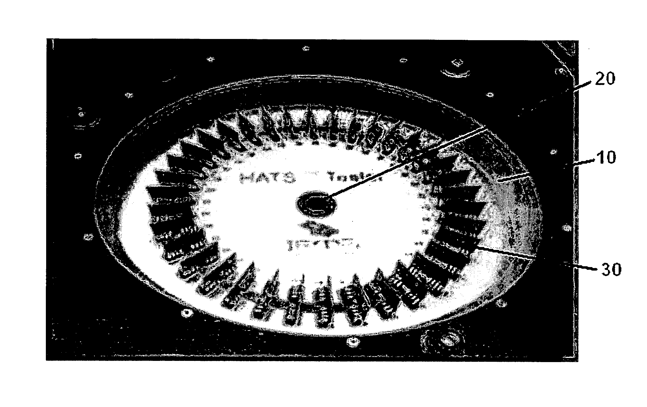
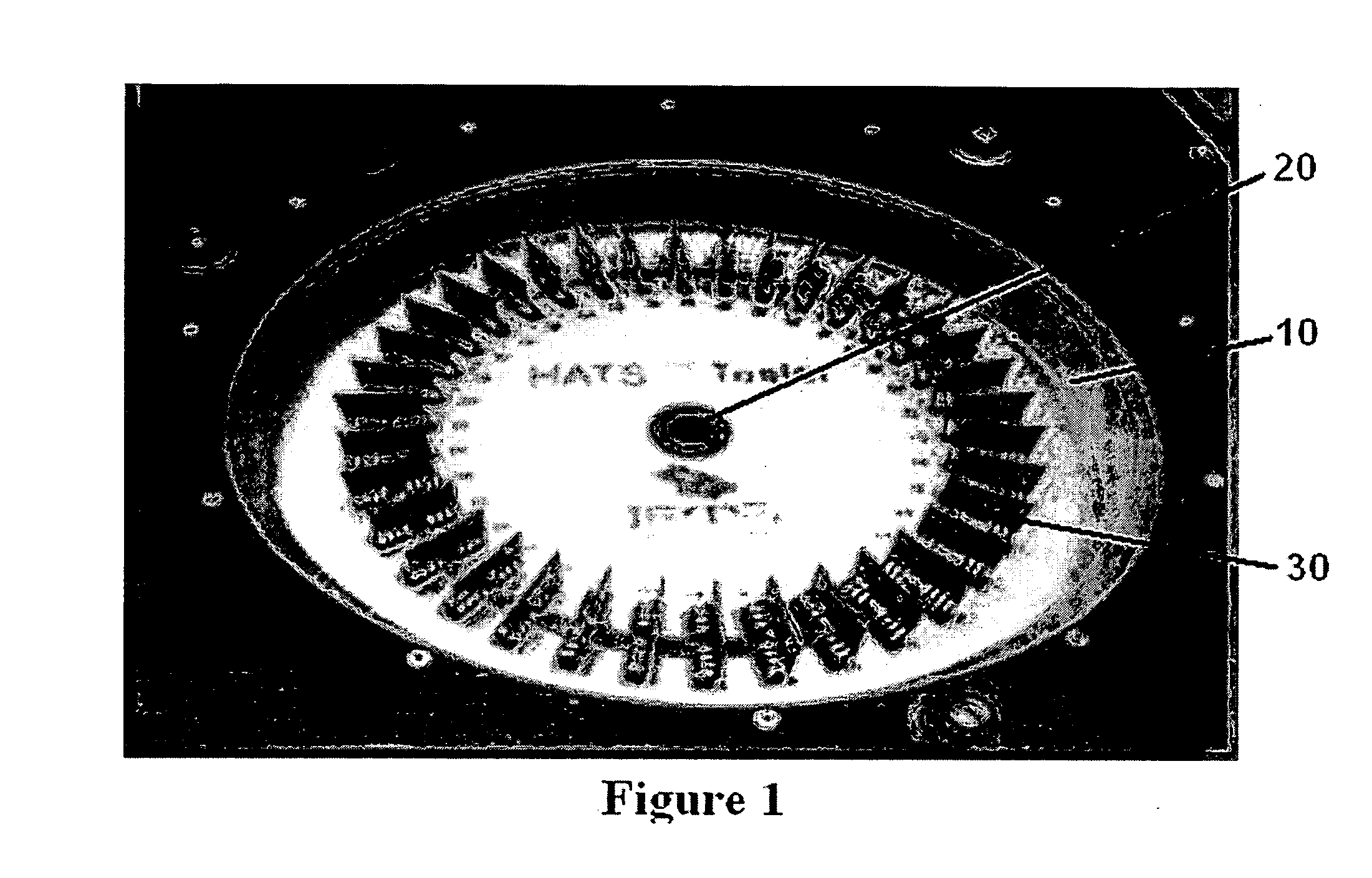
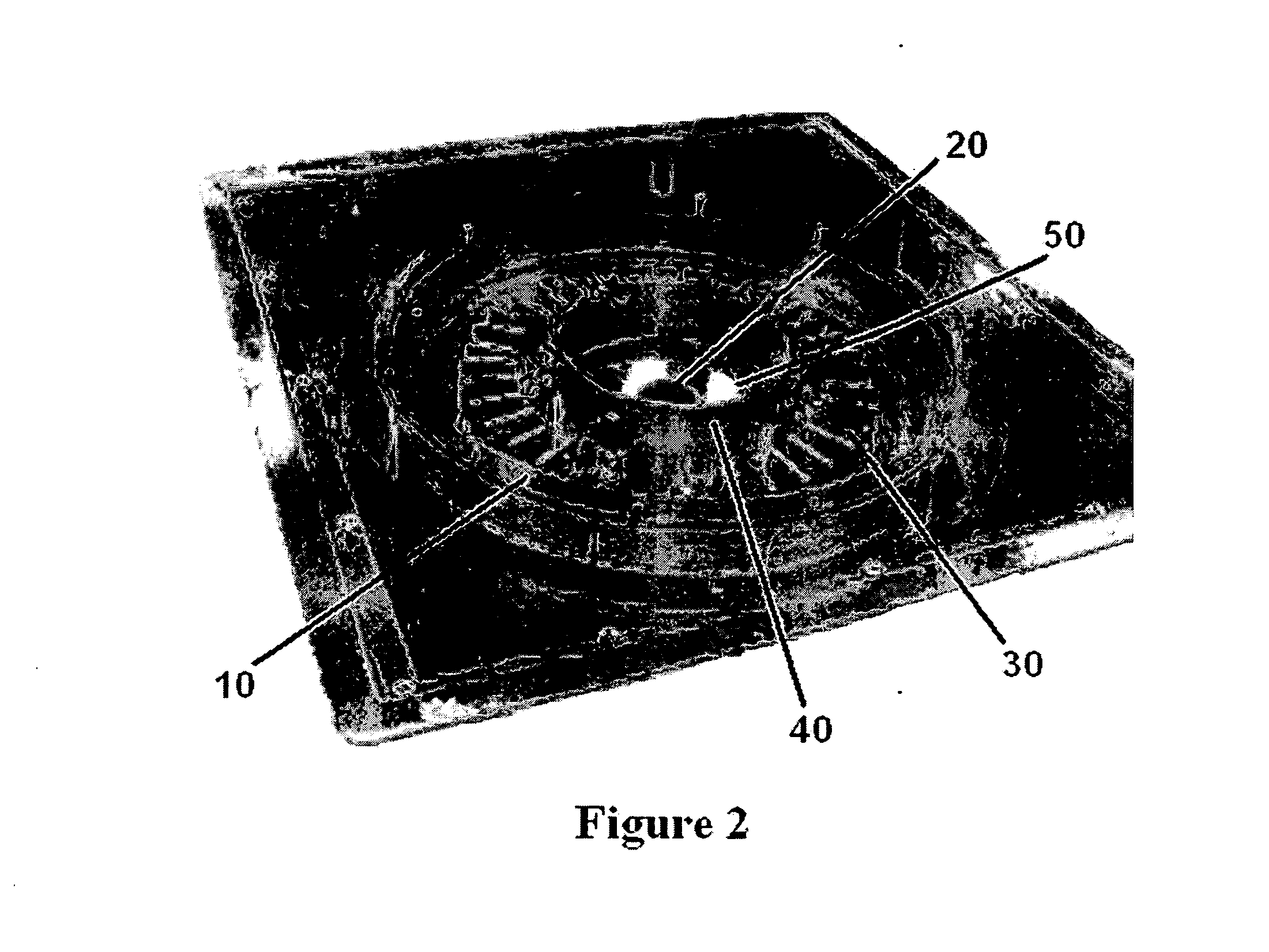
[0039] The example embodiment of the HATS system of the present invention was compared to two other systems: a Delphi two chamber air-to-air Thermal Shock system and an IST system. The HATS system has a temperature range of -60.degree. C. to +160.degree. C., with an air transition time between the two extremes of only thirty seconds. The system can accommodate 36 coupons, each with four independent nets, or circuits, providing 144 samples per test run.

[0040] For this particular example, the temperature was required to be cycled from -40.degree. C. to +145.degree. C. An example resistance trace for a net is shown in FIG. 4. The graph shows the resistance varying from a low value to a high value corresponding to the thermal cycling. The sharp increase in resistance as component failure starts to occur is clearly depicted. It is therefore impossible to monitor the resistance of the samples as a method of determining their temperature once such failure is initiated. For this test it too...


PUM


Abstract

An apparatus for rapid thermal testing of samples consisting of a single sample chamber in which the samples are preferably arranged circularly around the opening through which a fluid of varying temperature, preferably air, is introduced to provide for rapid, uniform cooling and heating of the samples. The samples are preferably uniformly spaced to allow for uniform air flow. The samples are mounted in slots which are preferably oriented radially outward from the opening. The sample mounts comprise electrical connectors which form a network connected to at least one ohmmeter for measuring the resistance of the samples. The samples preferably comprise test coupons, each with multiple daisy-chained nets of vias or other components to be tested. Also a method for thermal testing of samples consisting of steps to characterize the samples before the test is run. First, the resistance of the samples which correlates to each target temperature is determined, and the time required for the samples to reach that resistance when they are heated or cooled is measured. Then, for reliability testing, the temperature of the samples is cycled between the target temperatures, where the cycle segment durations are given by the times measured in the characterization steps.

Description

[0001] This application claims the benefit of the filing of U.S. Provisional Patent Application Serial No. 60 / 449,276, entitled "Highly Accelerated Thermal Shock", filed on Feb. 20, 2003, the specification of which is incorporated herein by reference.[0002] 1. Field of the Invention (Technical Field)[0003] The present invention relates to a method and apparatus for thermal shock reliability testing of electronic components such as printed circuit boards and solder joints. The present invention provides for testing the thermal reliability of devices in a time period which is up to ten times shorter than currently used tests.[0004] 2. Background Art[0005] Note that the following discussion is given for more complete background of the scientific principles and is not to be construed as an admission that such concepts or publications listed are prior art for patentability determination purposes.[0006] Thermal shock testing has long been the accepted method to check the reliability of pl...

Claims


Application Information

Patent Timeline
IPC IPC(8): G01N3/60G01N19/04G01R31/28
CPCG01N3/60G01N19/04G01R31/2817G01R31/2818
Inventor ESTES, TIMOTHY A.NEVES, ROBERT
Owner CONDUCTOR ANALYSIS TECH
Learn More