
Conveyor sealing plate

a sealing plate and conveyor technology, applied in the direction of conveyor parts, engine seals, engine components, etc., can solve the problems of strip wear, strip replacement, long and laborious operations,

Active Publication Date: 2010-09-21
SOC FINANCIERE DE TION
View PDF13 Cites 5 Cited by
  • Summary
  • Abstract
  • Description
  • Claims
  • Application Information

AI Technical Summary

Benefits of technology

[0019]The invention proposes a solution which facilitates the mounting and demounting of these strips for bulk material conveyors and which does not require lengthy cleaning operations prior to replacing the strip.

Problems solved by technology

Due to friction, wear occurs on the sealing strip, and the sealing strip must therefore be replaced.
These operations for replacing the strip are long and tedious.
It is also clear that manipulating these screws is made more difficult by dust which accumulates on the screw threads or by corrosion due to the nature or the wetness of these bulk materials.
This conveyor is not suitable for transporting bulk materials.
If that were the case, dust would accumulate in the female part, resulting in a need to remove the dust prior to replacing the strip.

Method used


Image

  • Conveyor sealing plate
  • Conveyor sealing plate

Examples


Embodiment Construction

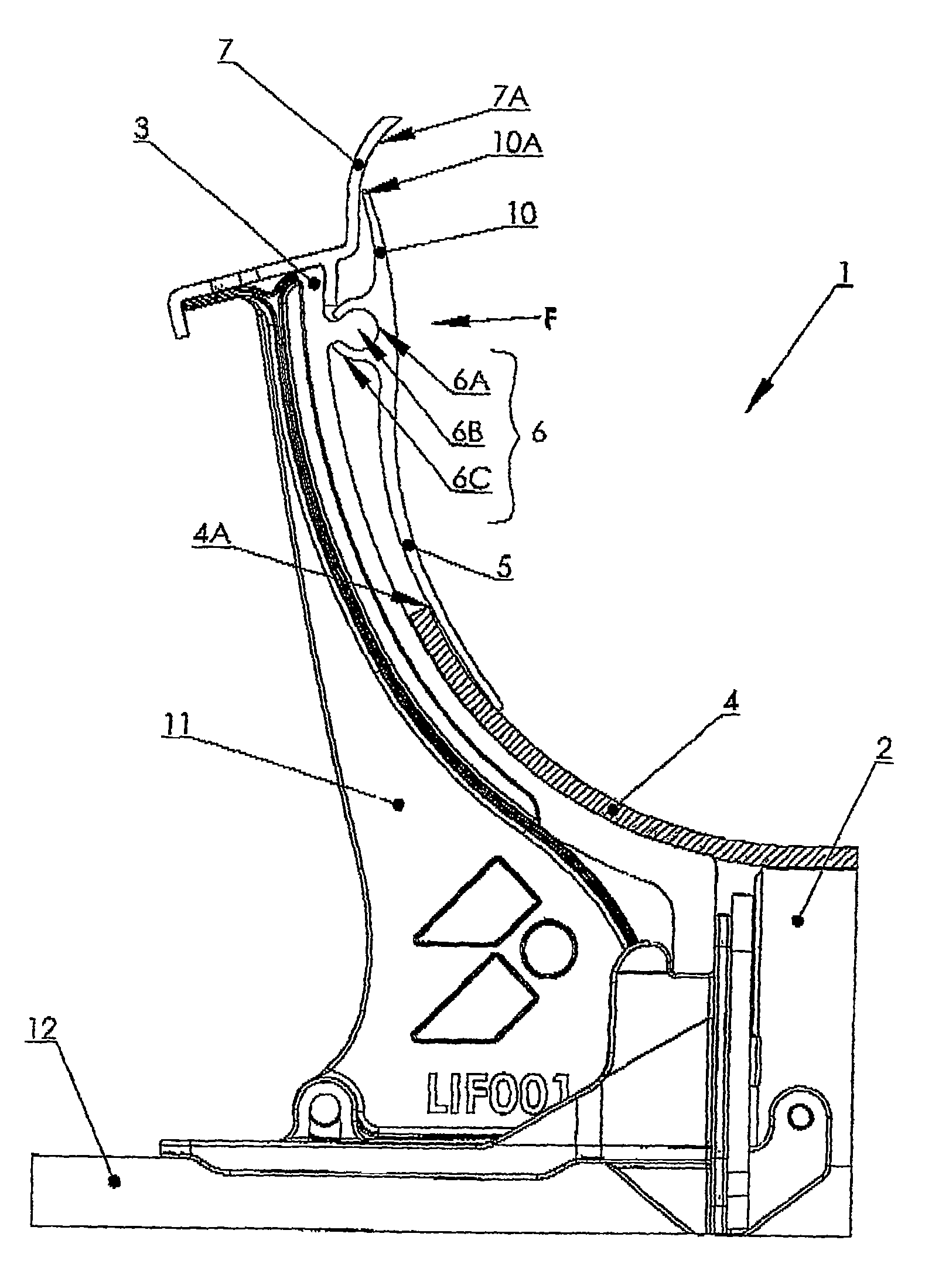
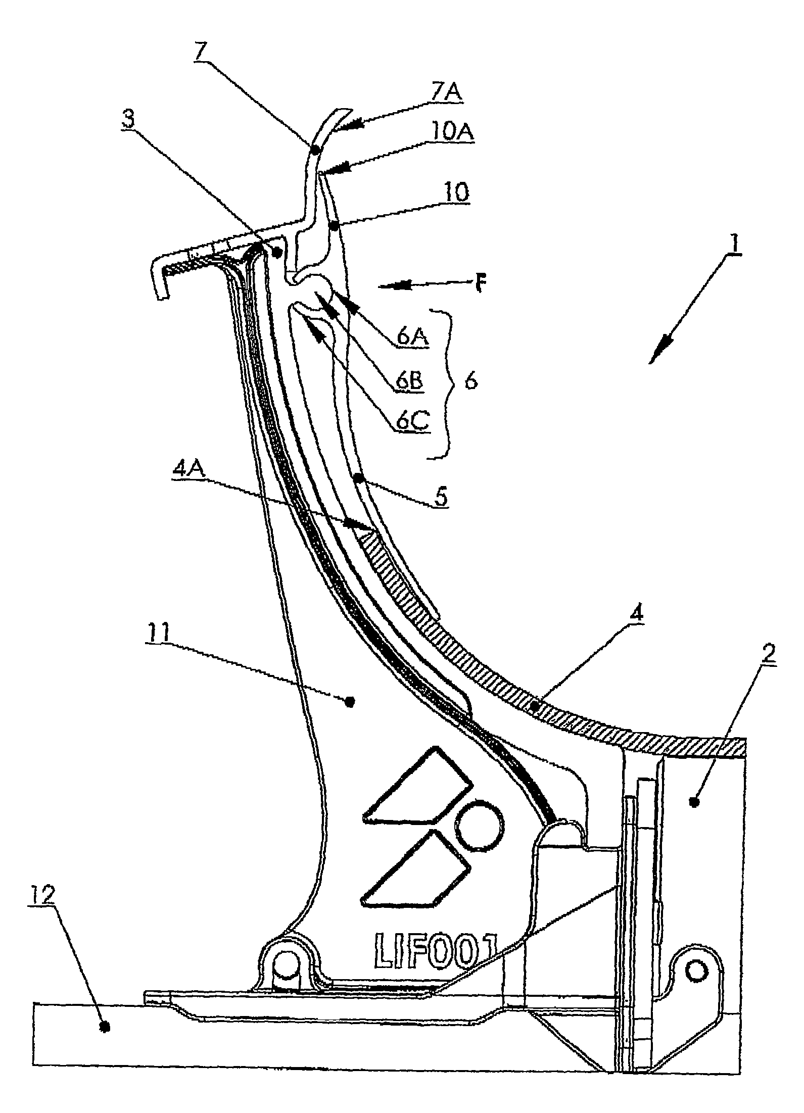
[0021]The invention will be more clearly understood with the help of the following description given as a nonlimiting example in reference to the drawing, which schematically illustrates a cutaway view of a conveyor equipped with a strip according to the invention.

[0022]Referring to the drawing, we see a bulk material conveyor 1.

[0023]This conveyor comprises means such that the conveyor belt with which it is equipped takes the shape of a trough or chute so as to be able to contain the bulk material.

[0024]In the example illustrated, the trough shape is defined by a roller 2 with a horizontal axis flanked by curved guide walls 3.

[0025]The lower surface of the endless belt 4 rests on the roller and glides over the lower part of the guide walls.

[0026]A sealing strip 5 is mounted on each guide wall, attached by its top part, and the bottom of this sealing strip overlaps the lateral edge 4A of the endless belt.

[0027]In order to be held in place on the conveyor, the strip 5 comprises a com...


PUM


Abstract

A sealing strip comprising a part of a configuration for fastening to a guide wall of a conveyor, the fastening configuration allowing for interlocking via elastic deformation of one of two parts of the fastening configuration.

Description

CROSS REFERENCE TO RELATED APPLICATIONS[0001]This application claims the benefit of PCT Application No. PCT / FR2007 / 000765, filed May 4, 2007, now pending, which claims the benefit of and priority to French Application No. 0604125, filed May 10, 2006, all of which are incorporated herein by reference in their entirety.BACKGROUND OF THE INVENTION[0002]The invention relates to a sealing strip for a trough-shaped conveyor.[0003]It also relates to the conveyor provided with said strip.[0004]The use of a belt conveyor to transport bulk materials from one place to another is known.[0005]This belt conveyor has a trough-shaped cross-section so that the belt that molds to this trough forms a chute capable of containing the bulk material.[0006]More particularly, there is a known conveyor whose cross-section is defined by a roller with a horizontal axis and curved so-called guide walls located on either side of the roller.[0007]The conveyor belt glides over these guide walls.[0008]The conveyor ...

Claims


Application Information

Patent Timeline
IPC IPC(8): B65G21/20
CPCB65G21/2081B65G21/22B65G21/20
Inventor SIMOENS, HERVE
Owner SOC FINANCIERE DE TION
Learn More