Jaw plate for a jaw crusher

Pending Publication Date: 2020-01-16
SANDVIK INTELLECTUAL PROPERTY AB
View PDF5 Cites 0 Cited by
  • Summary
  • Abstract
  • Description
  • Claims
  • Application Information

AI Technical Summary

Benefits of technology

The present invention provides a jaw plate that can be easily and reliably clamped at the jaw and quickly dismounted as required. The jaw plate is designed to work with a hidden retainer assembly that does not interfere with the crushing action. The mounting position of the jaw plate allows for a larger crushing chamber without increasing the overall crusher height, which reduces the overall weight of the crusher. The design also avoids the need for welding lifting ears onto the retainer assembly or the jaw plate, which allows for unrestricted growth of the jaw plate during use.

Problems solved by technology

Accordingly, the plate clamping mechanism is not subject to wear and moreover the significant disadvantages associated with fusing (or overlapping) of the clamping mechanism onto or around the jaw plate that would otherwise impede dismounting of the plate from the frame.

Method used


Image

  • Jaw plate for a jaw crusher
  • Jaw plate for a jaw crusher
  • Jaw plate for a jaw crusher

Examples


Embodiment Construction

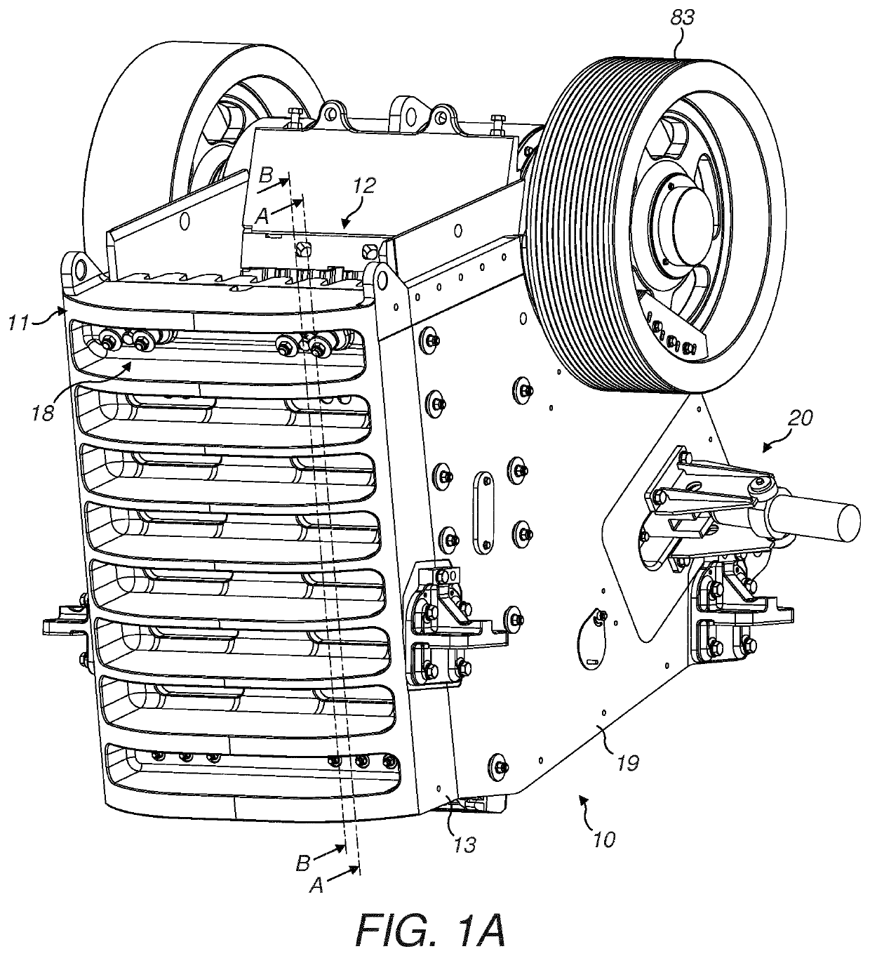
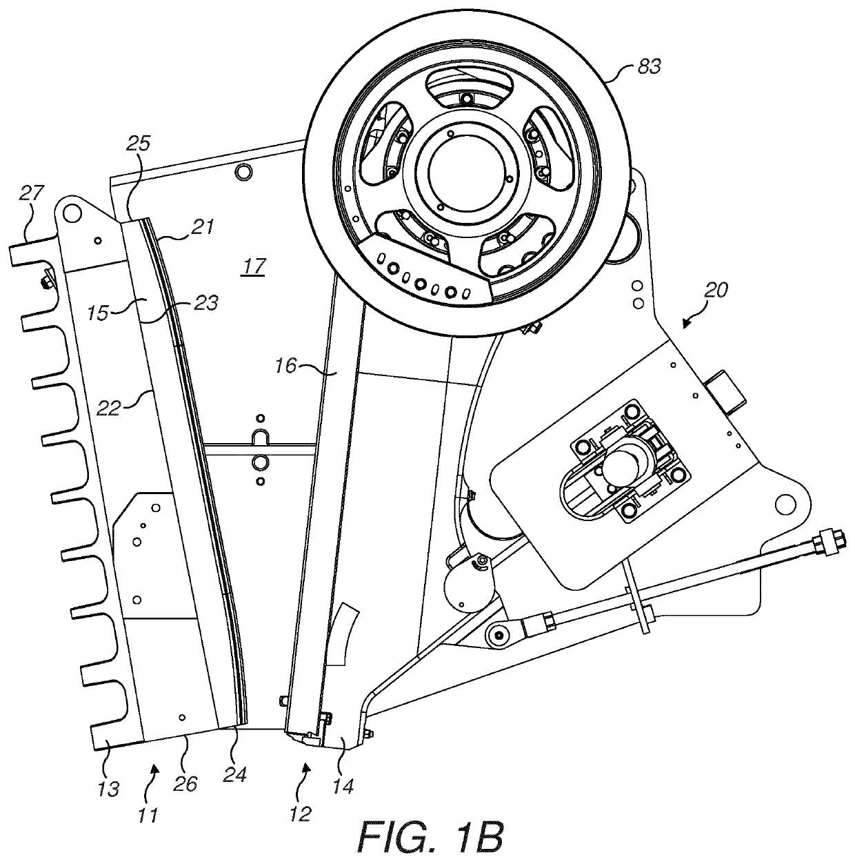
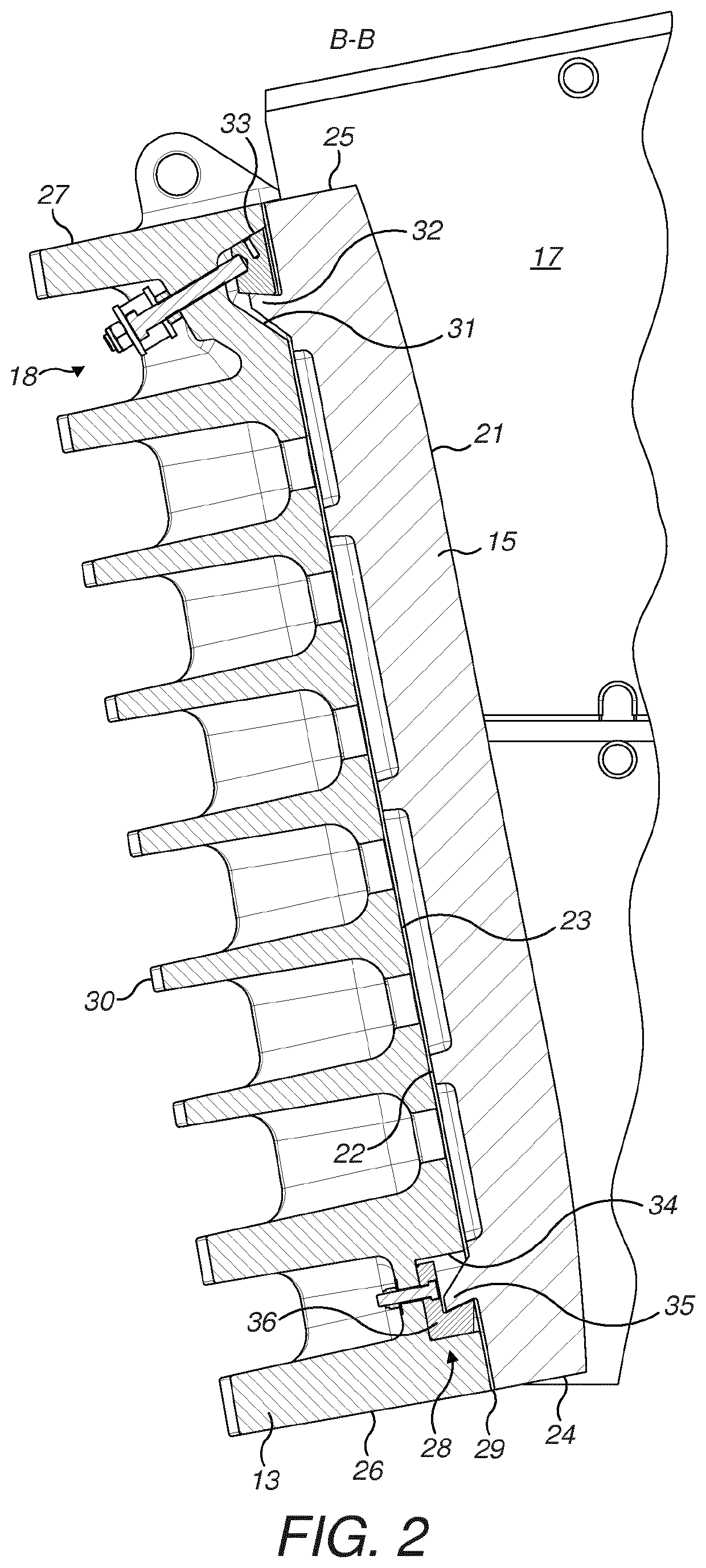
[0035]Referring to FIGS. 1A, 1B and 2, a jaw crusher 10 comprises a static jaw 11, commonly referred to as a front frame end positioned opposite a moveable jaw 12. The jaws 11, 12 between them and in combination with crusher side walls 19 (that in turn mount wear liner plates (not shown)) define a crushing chamber 17. The static jaw 11 comprises a frame 13 and a moveable jaw 12 similarly comprises a frame 14 with each frame 13, 14 mounting a respective jaw plate 15, 16. Each jaw plate 15, 16 comprises a generally planar crushing face 21 that may be regarded as front facing into the crushing chamber 17 and against which material is crushed by a reciprocating / oscillating motion of the moveable jaw 12 relative to stationary jaw 11. Referring to the jaw plate15 mounted at frame 13, plate 15 further comprises a rearward facing rear mount face 22 for mounting against a support face 23 of the frame 13 via contact with an intermediate liner plate 29. Plate 15 further comprises a first upper...


PUM


Abstract

A jaw plate for a jaw crusher has jaw mounting components positioned exclusively at a rear mount face of the plate. In particular, the jaw plate has at least the first and second mount flange projecting rearwardly from a rear mount face being engagable with respective retaining assemblies so releasably mount the plate at the jaw. The present jaw plate being arranged to prevent damage to the retaining assemblies during use.

Description

FIELD OF INVENTION[0001]The present invention relates to a jaw plate mountable at a jaw of a jaw crusher and in particular, although not exclusively, to a jaw plate facilitating mounting and dismounting at the jaw.BACKGROUND ART[0002]Jaw crusher units typically comprise a fixed jaw and a movable jaw that together define a crushing zone. A drive mechanism is operative to rock the movable jaw back and forth in order to crush material within this zone. The crushing zone is generally convergent towards its lower discharge end so that crushable material, fed to an upper and wider end of the zone, is capable of falling downward under gravity whilst being subject to repeated cycles of crushing movement in response to the cyclical motion of the movable jaw. The crushed material is then discharged under gravity through the lower discharge end onto a conveyor belt for onward processing or to a suitable stockpile.[0003]Commonly, the frame that supports the fixed jaw is referred to as the front...

Claims


Application Information

Patent Timeline
IPC IPC(8): B02C1/10B02C1/04
CPCB02C1/10B02C1/04
Inventor SJOBECK, ROGERLINDBERG, MARTEN
Owner SANDVIK INTELLECTUAL PROPERTY AB
Why Eureka
Try Eureka