Optical wavefront control pattern generating apparatus and optical wavefront control pattern generating method

a technology of optical wavefront and control pattern, applied in the direction of optical radiation measurement, material analysis through optical means, instruments, etc., can solve the problems of increasing the amount of computation with increasing the size of a hologram, noise is sometimes recognized in a reconstructed image, and the reconstructed image is computed through computer simulation, so as to achieve faster and more accurate results

Inactive Publication Date: 2010-09-21
NTT DOCOMO INC
View PDF10 Cites 0 Cited by
  • Summary
  • Abstract
  • Description
  • Claims
  • Application Information

AI Technical Summary

Benefits of technology

[0021]Consequently, the present invention has been made in consideration of the above points. An object of the present invention is to provide an optical wavefront control pattern generating apparatus and an optical wavefront control pattern generating method with which the problem with noise, which is practically insoluble with software, can be solved through processing with hardware, and with which a desired reconstructed image can be obtained faster and more accurately.

Problems solved by technology

However, in a method of computing a solution obtained after each of Move operations on the basis of difference information with a solution prior to the Move operation as in the case of conventional Non-patent Document 2, even if an amount of computation for a solution obtained after each of the individual Move operations can be reduced to the linear order, a fundamental problem that an amount of computation increases with increasing size of a hologram cannot be solved.
Accordingly, noise is sometimes recognized in a reconstructed image in a case where the characteristics of the optical wavefront control device are different from those expected, or due to such reasons as minute individual variability existing in actual equipment.
As a result, there has been a problem that a reconstructed image which is computed through computer simulation, and a reconstructed image which is reconstructed by incorporating a computer generated hologram into an actual image reconstruction system (an optical system) are not necessarily identical to each other.
However, it is not necessarily possible to modulate only a phase of light, and the amplitude of light is also modulated more or less.
Thereby, a problem with noise in the reconstructed image is more conspicuous.
The above problems occur as a result of approximately obtaining a computer generated hologram under ideal conditions.
However, it is very difficult, and unrealistic, to strictly pursue causes of noise in the reconstructed image, the noise occurring in the real world, and to model elements of noises in a way that the elements are manageable on a computer.

Method used


Image

  • Optical wavefront control pattern generating apparatus and optical wavefront control pattern generating method
  • Optical wavefront control pattern generating apparatus and optical wavefront control pattern generating method
  • Optical wavefront control pattern generating apparatus and optical wavefront control pattern generating method

Examples


first embodiment

Configuration of Optical Wavefront Control Pattern Generating Apparatus According to the Present Invention

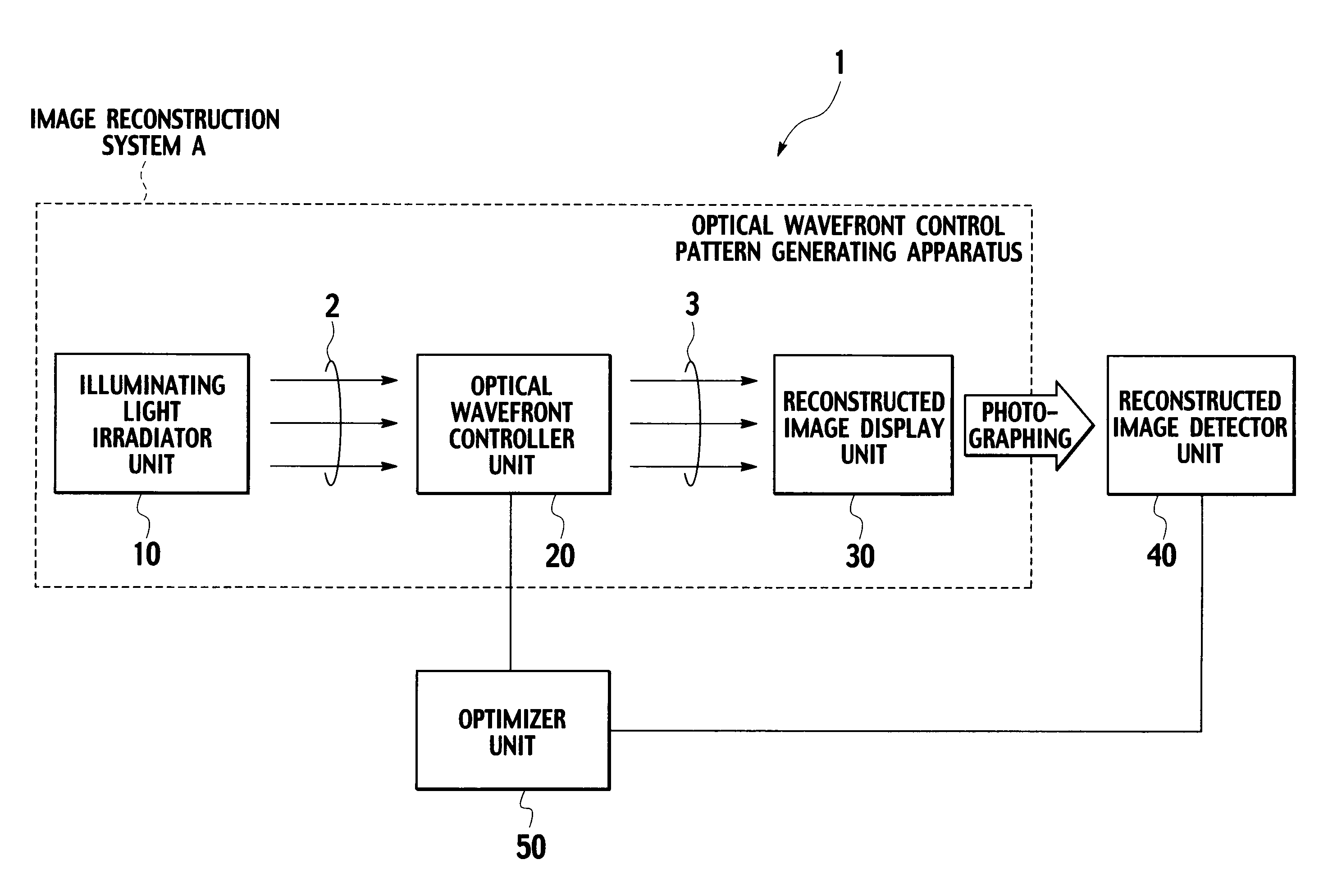
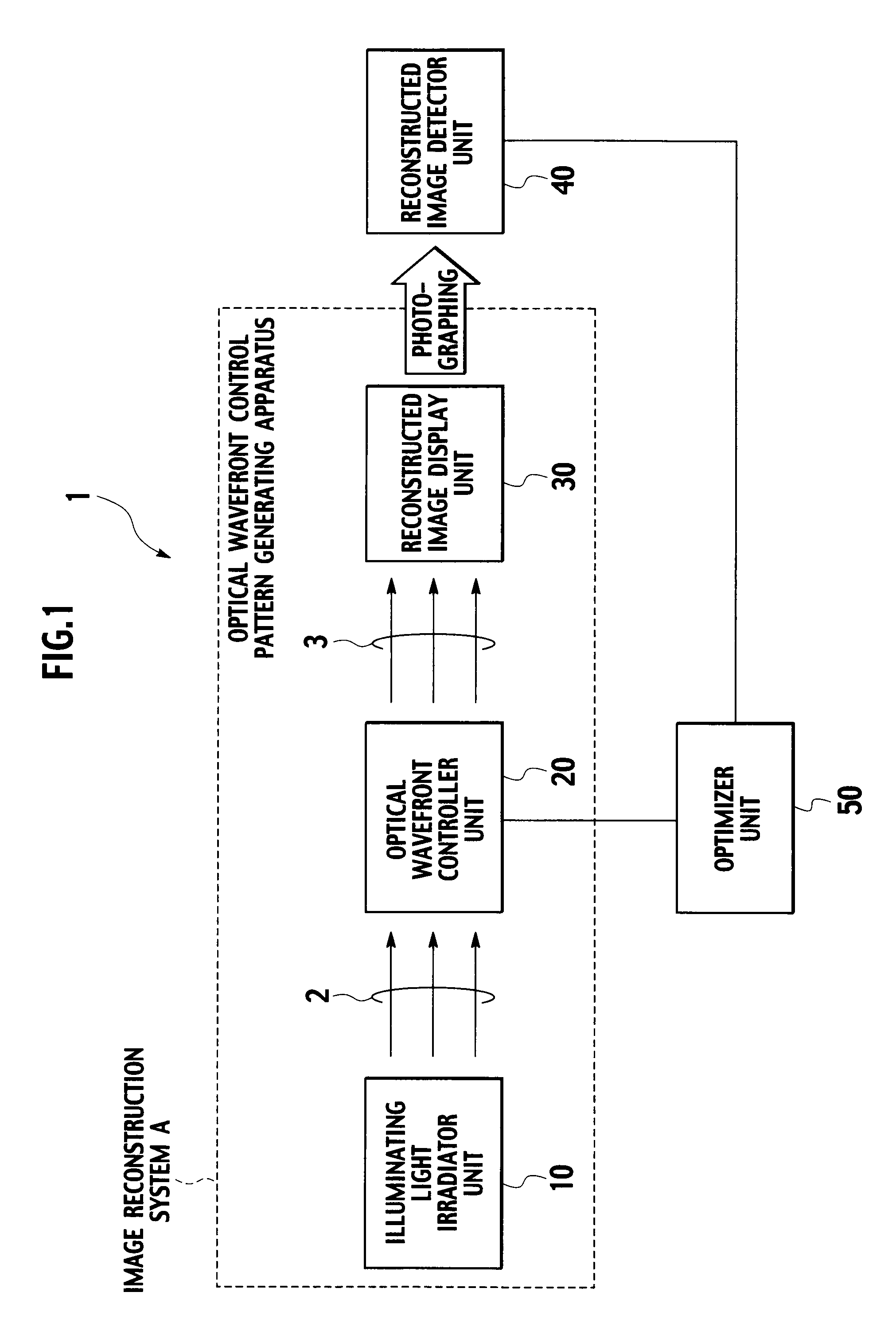
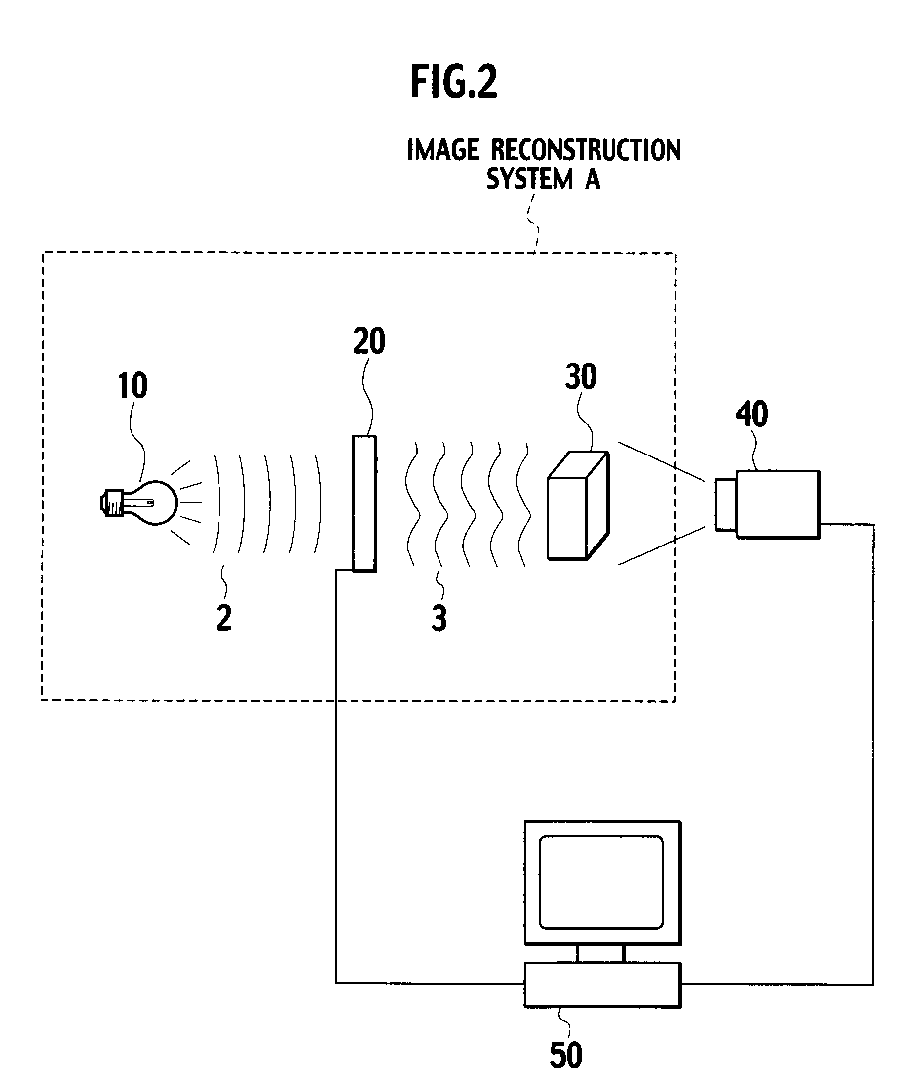
[0038]With reference to FIGS. 1 to 3, descriptions will be provided for a configuration of an optical wavefront control pattern generating apparatus 1 according to a first embodiment of the present invention. By irradiating an optical wavefront controller unit 20, in which the optimum optical wavefront control pattern is recorded, with illuminating light 2, the optical wavefront control pattern generating apparatus 1 according to this embodiment is configured to generate the optimum optical wavefront control pattern, which is to be stored in the optical wavefront controller unit 20, in an image reconstruction system A for displaying a reconstructed image on a reconstructed image display unit 30.

[0039]As shown in FIGS. 1 and 2, the optical wavefront control pattern generating apparatus 1 according to this embodiment includes an illuminating light irradiator unit 10, the optical w...

second embodiment

Optical Wavefront Control Pattern Generating Apparatus According to the Present Invention

[0103]With reference to FIGS. 5(a) and 5(b), an optical wavefront control pattern generating apparatus according to a second embodiment of the present invention will be described.

[0104]As shown in FIG. 5(a), in the optical wavefront control pattern generating apparatus according to the second embodiment, the optical wavefront controller unit 20 is configured to modulate at least any one of an amplitude and a phase of illuminating light irradiated by the illuminating light irradiator unit 10. The reconstructed image display unit 30 is configured to display a reconstructed image based on reconstruction light 2 obtained by modulating at least any one of the amplitude and the phase of the illuminating light.

[0105]Here, the reconstructed image detector unit 40 includes a plurality of sensors (for example, CCD cameras) which make it possible to detect the reconstructed image displayed on the reconstru...


PUM

PropertyMeasurementUnit
phaseaaaaaaaaaa
temperatureaaaaaaaaaa
sizeaaaaaaaaaa

Abstract

An optical wavefront control pattern generating apparatus includes: a reconstructed image detector unit configured to detect a reconstructed image displayed on the reconstructed image display; and an optimizer unit configured to evaluate the reconstructed image detected by the reconstructed image detector unit, and to generate the optimum optical wavefront control pattern by applying a modification process to the optical wavefront control pattern in order for a result of the evaluation to satisfy a predetermined condition.

Description

TECHNICAL FIELD[0001]The present invention relates to an optical wavefront control pattern generating apparatus and an optical wavefront control pattern generating method which generate an optimum optical wavefront control pattern which is to be stored in an optical wavefront controller unit, in an image reconstruction system displaying a reconstructed image on a reconstructed image display unit, by irradiating the optical wavefront controller unit, in which an optical wavefront control pattern is recorded, with illuminating light.BACKGROUND ART[0002]Conventionally, “holography” has been known as a technology for displaying a reconstructed image on a reconstructed image display unit, by irradiating an optical wavefront controller unit, in which an optical wavefront control pattern (a hologram) is recorded, with illuminating light.[0003]The “holography” is a technology for reconstructing an optical wavefront itself of an object beam, by controlling at least any one of a phase and an ...

Claims


Application Information

Patent Timeline
Patent Type & Authority Patents(United States)
IPC IPC(8): G02B27/52G03H1/00G06K9/76G03B15/00G02B27/22G02F1/13G03H1/04G03H1/08G03H1/22
CPCG03H1/00G03H1/0486G03H1/0808G03H1/22G03H1/2294G03H2001/0491G03H2001/2244G03H1/04
Inventor TSUBOI, MASASHIHORIKOSHI, TSUTOMU
Owner NTT DOCOMO INC
Why Eureka
Try Eureka