
Multi-piston camwheel engine

a camwheel engine and multi-piston technology, applied in the field of engines, can solve the problems low reliability, and low efficiency, and achieve the effects of low fuel economy, reliability, and efficiency

Inactive Publication Date: 2010-10-19
KUZWE
View PDF22 Cites 1 Cited by
  • Summary
  • Abstract
  • Description
  • Claims
  • Application Information

AI Technical Summary

Benefits of technology

[0005]Accordingly, the engine design presented herein includes reciprocating pistons in a radial design that operate without connecting rods or a crankshaft. The problems related to the traditional engine design including discrete efficiency, low fuel economy, and fallible reliability brought about by inherent design limitations are therefore reduced or eliminated. Further, a rotary engine of the type presented herein offers particular advantages over the traditional engine. By way of example, the reciprocating movement of the piston occurs on a line parallel to the axis of rotation of the output shaft. Accordingly, the piston is not acting against centrifugal force resulting from the rotational output of the engine. The arrangement of cylinders on axes parallel to the rotation of the output shaft results in a very compact engine for a given total displacement, which is enhanced moreover by the absence of crankshafts and associated parts found in a traditional engine. Appreciable weight savings are made as well with respect to the minimum parts required.

Problems solved by technology

The problems related to this design include discrete efficiency, low fuel economy, and fallible reliability brought about by inherent design limitations; namely, consequential problems caused by the inertia of the connecting rods, the adequate balancing of the crank shaft, along with the relative arrangement of their associated supports, and finally, by the placement of the valves and camshaft.

Method used


Image

  • Multi-piston camwheel engine
  • Multi-piston camwheel engine
  • Multi-piston camwheel engine

Examples


Embodiment Construction

[0020]While the making and using of various embodiments of the present invention are discussed in detail below, it should be appreciated that the present invention provides many applicable inventive concepts which can be embodied in a wide variety of specific contexts. The specific embodiments discussed herein are merely illustrative of specific ways to make and use the invention, and do not delimit the scope of the present invention.

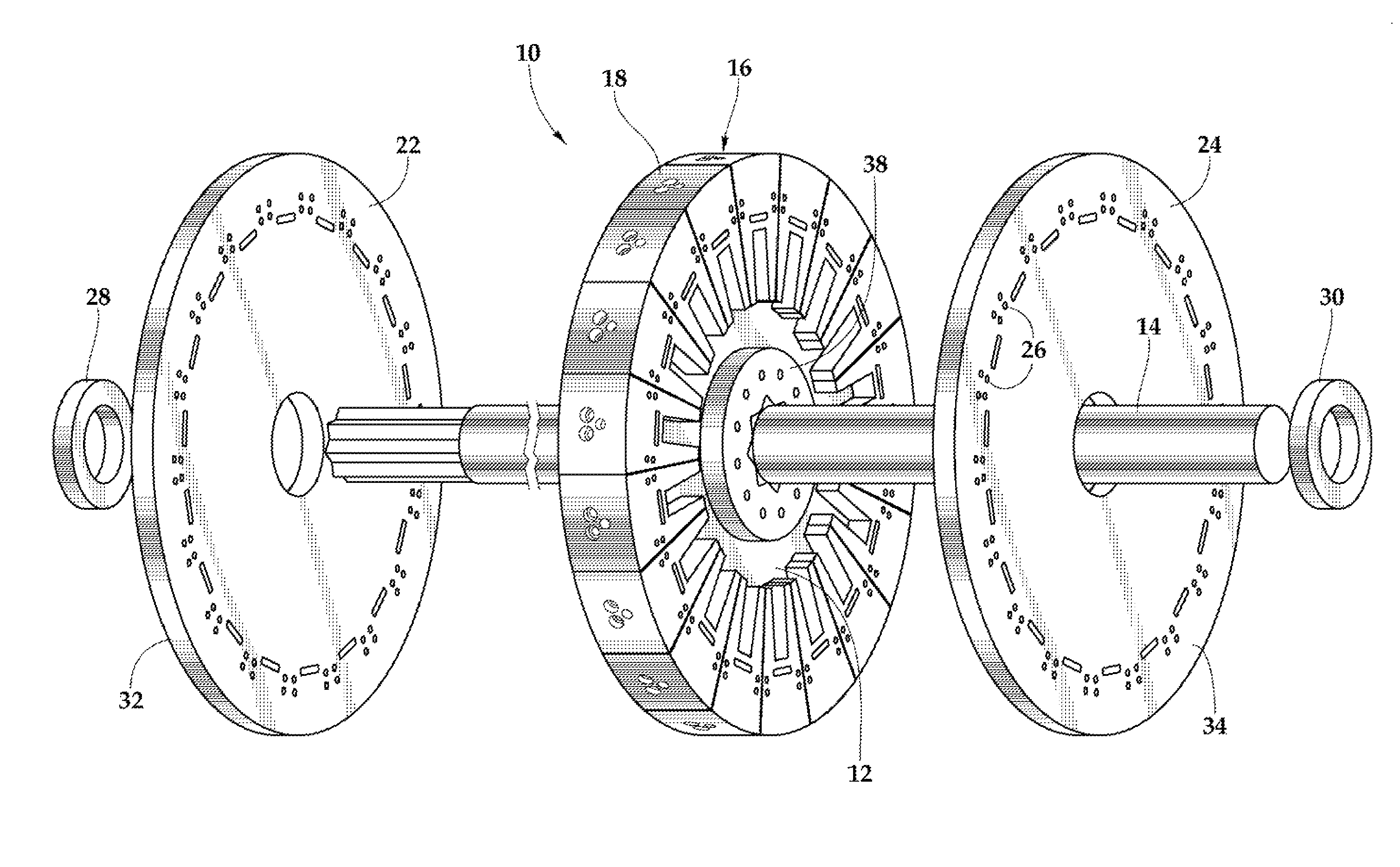
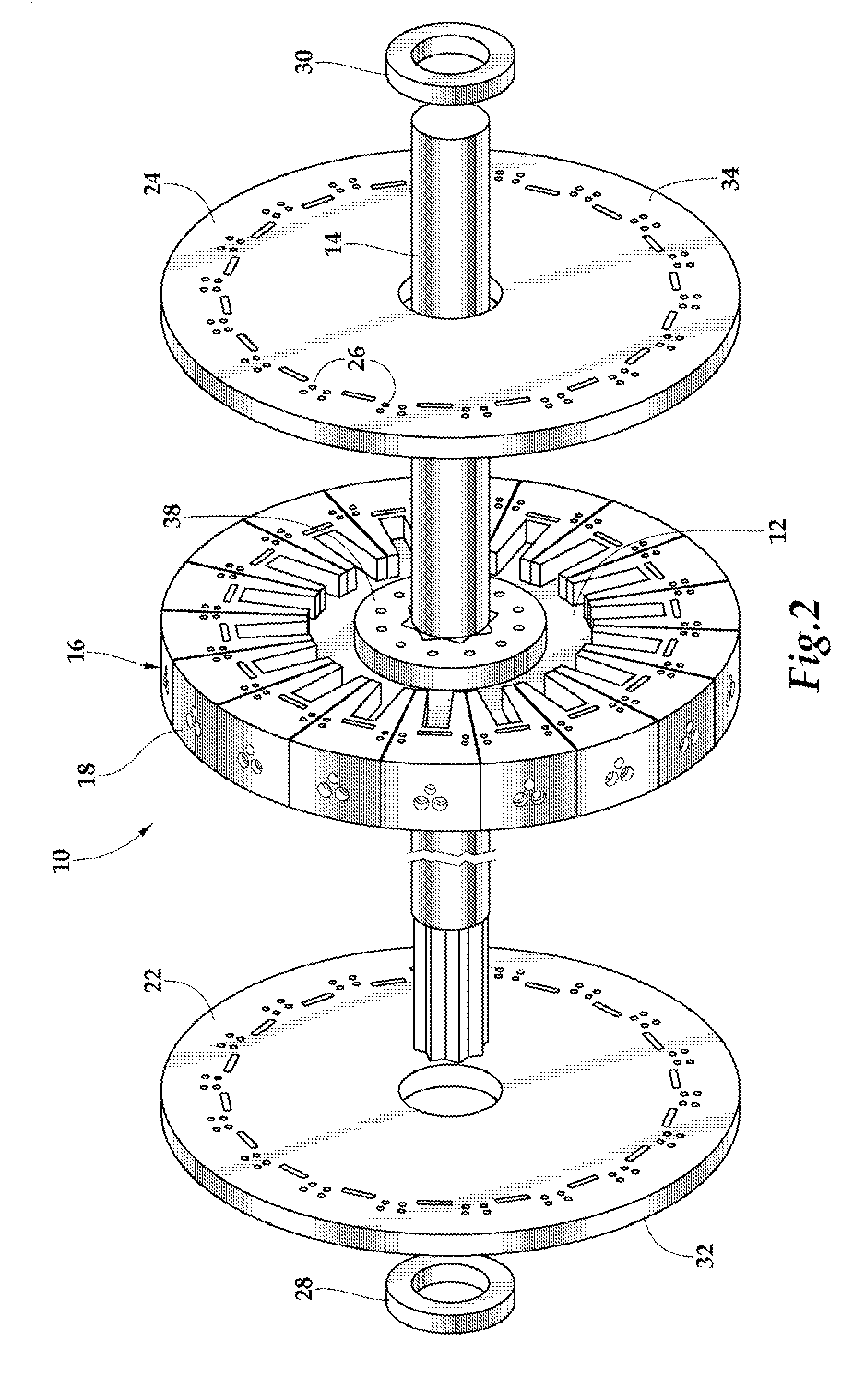
[0021]Referring initially to FIGS. 1, 2, and 3, therein one embodiment of an engine is depicted that is schematically illustrated and generally designated 10. A camwheel 12 is rotatably mounted to an output shaft 14, which may in turn be connected to any type of load. A cylinder block 16 including 18 cylinders, 18-1 through 18-18, which are collectively referenced by the number 18, is concentrically disposed about the camwheel 12. Eighteen pistons 20-1 through 20-18, which are collective cylinder-enclosed pistons 20, are respectively disposed within the...


PUM


Abstract

An engine is disclosed. In one implementation, the engine includes a camwheel mounted to an output shaft. Eighteen cylinder-enclosed pistons are positioned in a circular plane about the camwheel such that the radius of the circular plane and the camwheel are coplanar. Lobes integrally formed on the camwheel define a guiderail including a continuously, substantially sinusoidal surface biased for rotation in the direction of the rotary motion of the output shaft. Drive bearings associated with each piston engage and maintain contact with the guiderail. The rotary motion is obtained by transferring the displacement of the plurality of pistons from respective top dead center positions and bottom dead center positions to the guiderail, thereby rotating the camwheel and output shaft.

Description

PRIORITY STATEMENT & CROSS-REFERENCE TO RELATED APPLICATIONS[0001]This application claims priority from the following U.S. patent applications: (1) Application Ser. No. 60 / 823,373, entitled “Engine” and filed on Aug. 23, 2006, in the names of Maguire et al.; and (2) Application Ser. No. 60 / 948,672, entitled “Engine” and filed on Jul. 9, 2007 in the names of Maguire et al.; both of which are hereby incorporated by reference for all purposes.TECHNICAL FIELD OF THE INVENTION[0002]This invention relates, in general, to engines and, in particular, to internal combustion engines that convert combustion energy into rotational energy without the use of a traditional crankshaft.BACKGROUND OF THE INVENTION[0003]Traditional engines operate by transforming the displaced motion of a piston into rotary motion of a shaft by utilizing a system of connecting rods and a crank shaft. The problems related to this design include discrete efficiency, low fuel economy, and fallible reliability brought abo...

Claims


Application Information

Patent Timeline
Patent Type & Authority Patents(United States)
IPC IPC(8): F02B75/22
CPCF02B53/02F02B75/32Y02T10/17Y02T10/12
Inventor MAGUIRE, PAUL R.LINKEL, DION B.
Owner KUZWE
Learn More