Connector device

a technology of connecting device and shielding function, which is applied in the direction of coupling device connection, two-part coupling device, electrical apparatus, etc., can solve the problems of difficult to obtain a sufficient shielding function for each signal terminal, noise problem becomes a serious issue, and more apparent noise problem

Inactive Publication Date: 2010-10-19
HIROSE ELECTRIC GROUP
View PDF7 Cites 24 Cited by
  • Summary
  • Abstract
  • Description
  • Claims
  • Application Information

AI Technical Summary

Benefits of technology

[0004]In view of the problems described above, an object of the present invention is to provide a connector device with a higher shielding function for each signal terminal, thereby making it possible to effectively transmit a high-frequency signal.

Problems solved by technology

When the signal speed becomes faster, a noise problem becomes more apparent.
Especially when a high-frequency signal is transmitted, the noise problem becomes a serious issue.
In the conventional connector device described above, however, it is difficult to obtain a sufficient shielding function for each of the signal terminals.

Method used


Image

  • Connector device
  • Connector device
  • Connector device

Examples


first embodiment

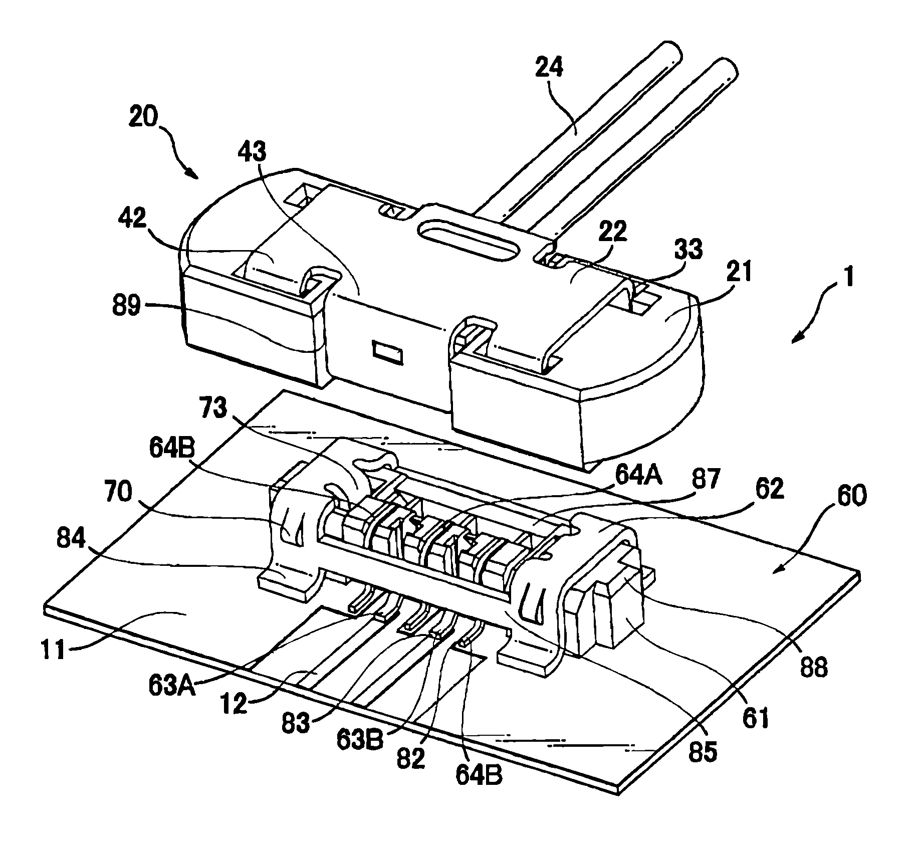
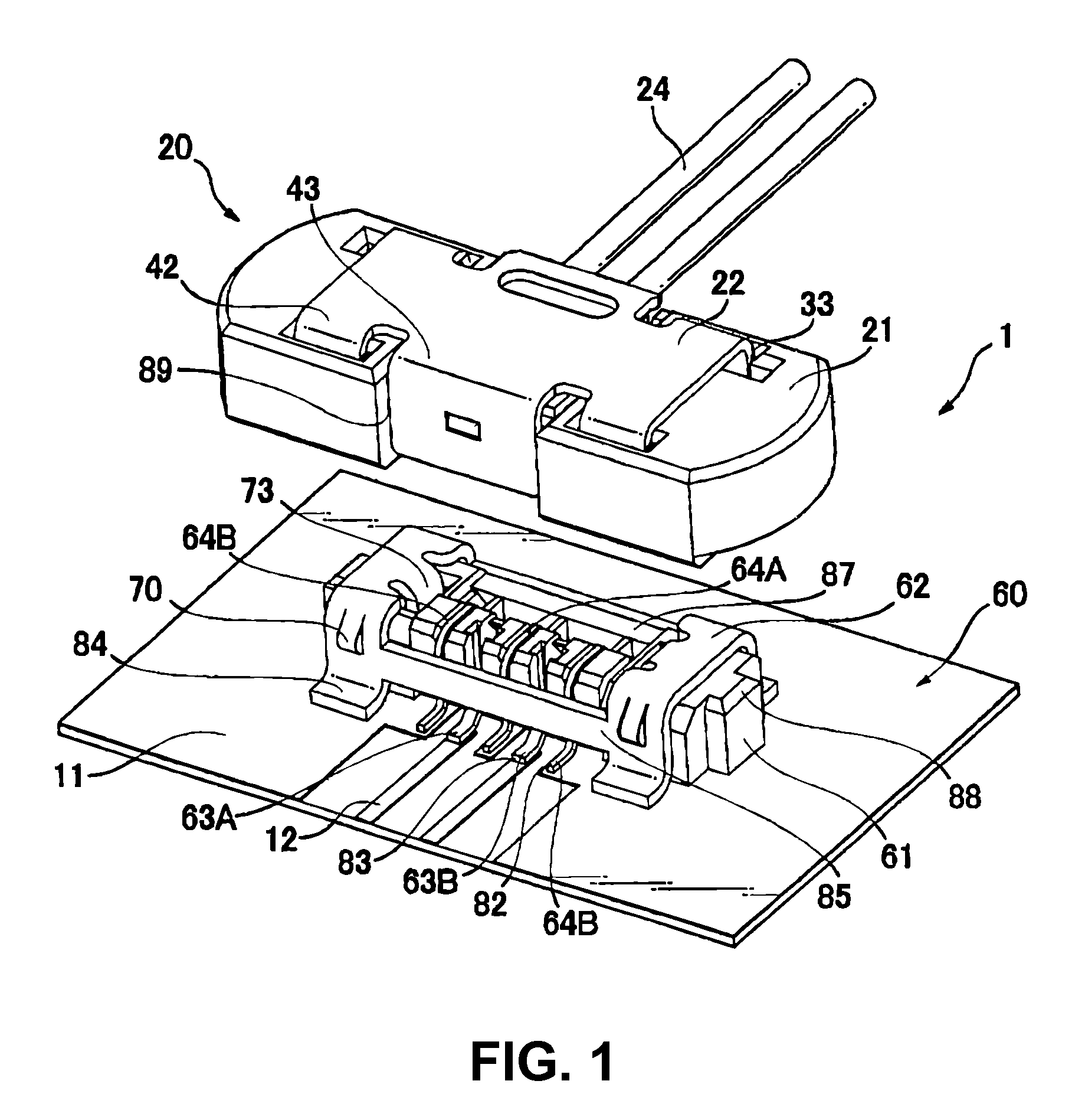
[0027]A first embodiment of the present invention will be explained. FIG. 1 is a perspective view showing a plug connector 20 and a receptacle connector 60 in a state before the plug connector 20 is connected to the receptacle connector 60 according to a first embodiment of the present invention. FIG. 2 is a perspective view showing the plug connector 20 and the receptacle connector 60 in a state after the plug connector 20 is connected to the receptacle connector 60 according to the first embodiment of the present invention.

[0028]As shown in FIGS. 1 and 2, a connector device 1 includes the plug connector (a first connector) 20 and the receptacle connector (a second connector or a receptacle) 60 to be connected to the plug connector 20. In the embodiment, the plug connector 20 is connected a coaxial cable 24 and the receptacle connector 60 is connected to a print board 11. In the present invention, it is not limited to a configuration described above.

[0029]Between the plug connector...

second embodiment

[0063]A second embodiment of the present invention will be explained next.

[0064]In the first embodiment, the slit 30 is provided between the protruding portions 37 for fixing the plug signal terminals 23. The present invention is not limited to the first embodiment.

[0065]FIG. 11 is a sectional view showing a plug connector 20C and a receptacle connector 60C according to a second embodiment of the present invention.

[0066]As shown in FIG. 11, as well as a slit 30C between protruding portions 37C of a plug housing 21C, a slit 30C′ can be added to a main body portion 21C. In FIG. 11, each component corresponding to the component in FIG. 1 and so on has a corresponding number followed by suffix “C”.

[0067]In the embodiment shown in FIG. 11, a ground terminal 64C has a larger step portion 91C and protrudes a larger portion 92C thereof toward a plug connector 20C so as to correspond to the slot 30C′. Thus the larger portion 92C protrudes from an upper portion of a receptacle shell 62C. Acco...


PUM


Abstract

A connector device includes a first connector and a second connector to be connected the first connector. The first connector includes a first housing, a plurality of first signal terminals arranged in the first housing, and a first shell for covering an outer portion of the first housing. The second connector includes a second housing, a plurality of second signal terminals arranged in the second housing, a second shell for covering an outer portion of the second housing, and a first ground terminal disposed between the second signal terminals for separating the second signal terminals. When the first connector is connected the second connector, the first signal terminals contact with the second terminals.

Description

BACKGROUND OF THE INVENTION AND RELATED ART STATEMENT[0001]The present invention relates to a connector device having a shielding function.[0002]These days, a signal is transmitted at a faster signal speed. When the signal speed becomes faster, a noise problem becomes more apparent. Especially when a high-frequency signal is transmitted, the noise problem becomes a serious issue. Japanese Patent Publication, for example, has disclosed a conventional connector device having a high shielding function against an electromagnetic disturbance or static electricity in order to resolve the noise problem. Patent Reference: Japanese Patent Publication No. 2008-147020[0003]In the conventional connector device disclosed in Patent Reference, some of a plurality of terminals maintain a shape approximately the same as that of the other terminals, and are used as a ground terminal instead of a signal terminal, thereby increasing a shielding performance thereof. In the conventional connector device ...

Claims


Application Information

Patent Timeline
Patent Type & Authority Patents(United States)
IPC IPC(8): H01R13/648
CPCH01R12/716
Inventor TSUCHIDA, MASAHIROSAWAI, TAKASHI
Owner HIROSE ELECTRIC GROUP
Why Eureka
Try Eureka