Striking tool

a tool and strike technology, applied in the field of striking tools, can solve the problems of vibration and noise generation, the buffer member b>242/b> cannot absorb nor buffer the impact force in the other direction, etc., and achieve the effects of reducing vibration and nois

Active Publication Date: 2010-10-26
KOKI HLDG CO LTD
View PDF22 Cites 28 Cited by
  • Summary
  • Abstract
  • Description
  • Claims
  • Application Information

AI Technical Summary

Benefits of technology

[0013]It is an object of the invention to provide a striking tool which can realize small vibration and low noise.
[0035]By thus configuration, the buffer member sandwiches therebetween the attachment portion of the cylinder casing to the casing in the state that the buffer member is compressed. Thus, when the cylinder casing moves, it is possible to suppress the generation of spaces in the axial direction of the tool between the buffer member and the attachment portion and also between the buffer member and the cylinder casing, thereby to realize the striking tool with further low noise and further small vibration.

Problems solved by technology

As a result, there is a drawback that the buffer member 242 can not absorb nor buffer an impact force in the other direction.
Thus, there arises a problem that vibration and noise are generated also by the impact force in the radial direction.

Method used


Image

  • Striking tool
  • Striking tool
  • Striking tool

Examples


Embodiment Construction

[0045]Hereinafter, an embodiment of the invention will be explained with reference to the accompanying drawings.

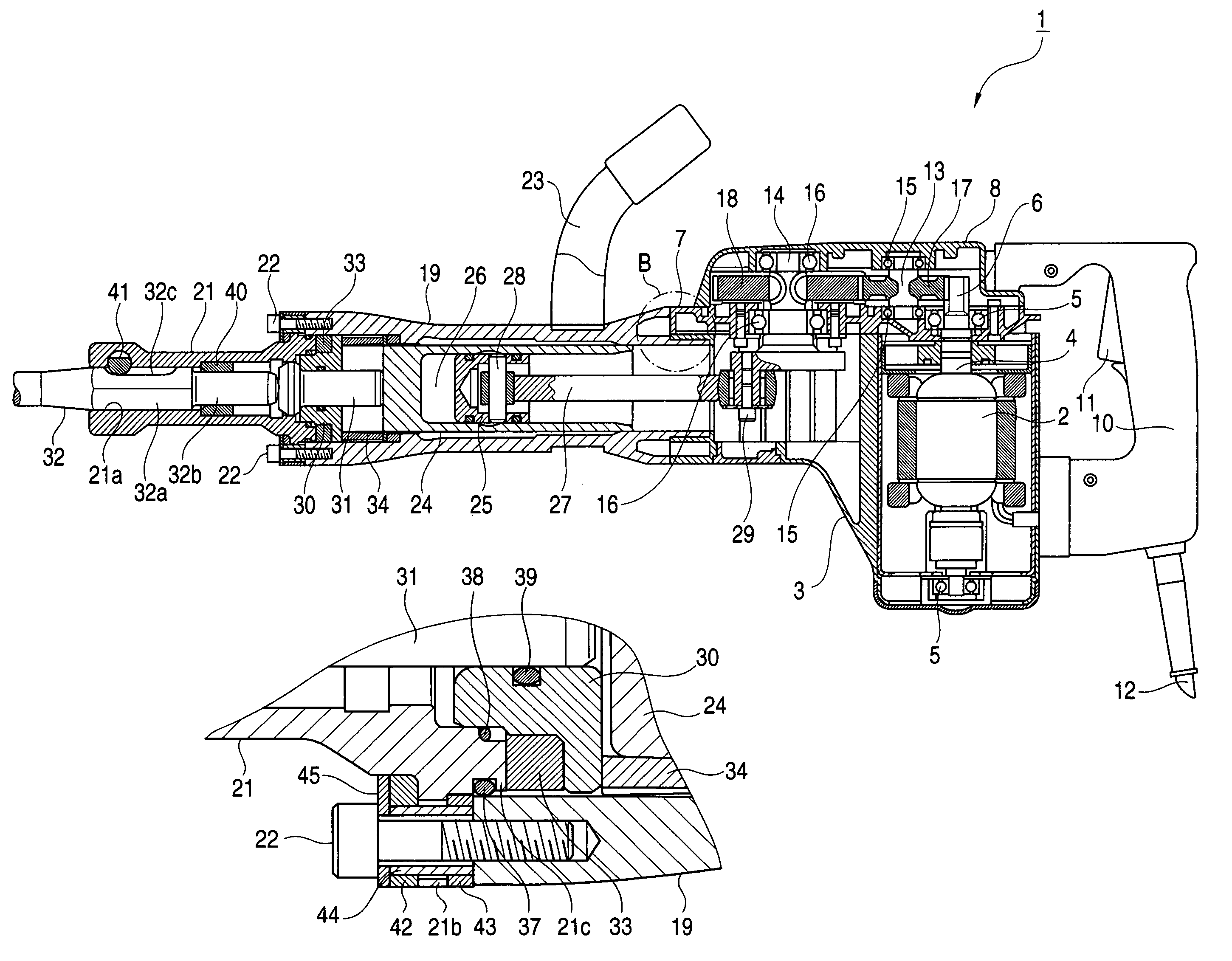
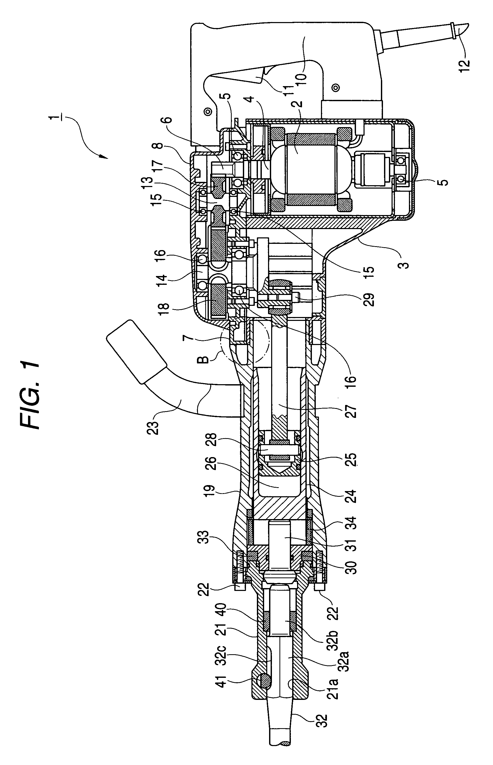
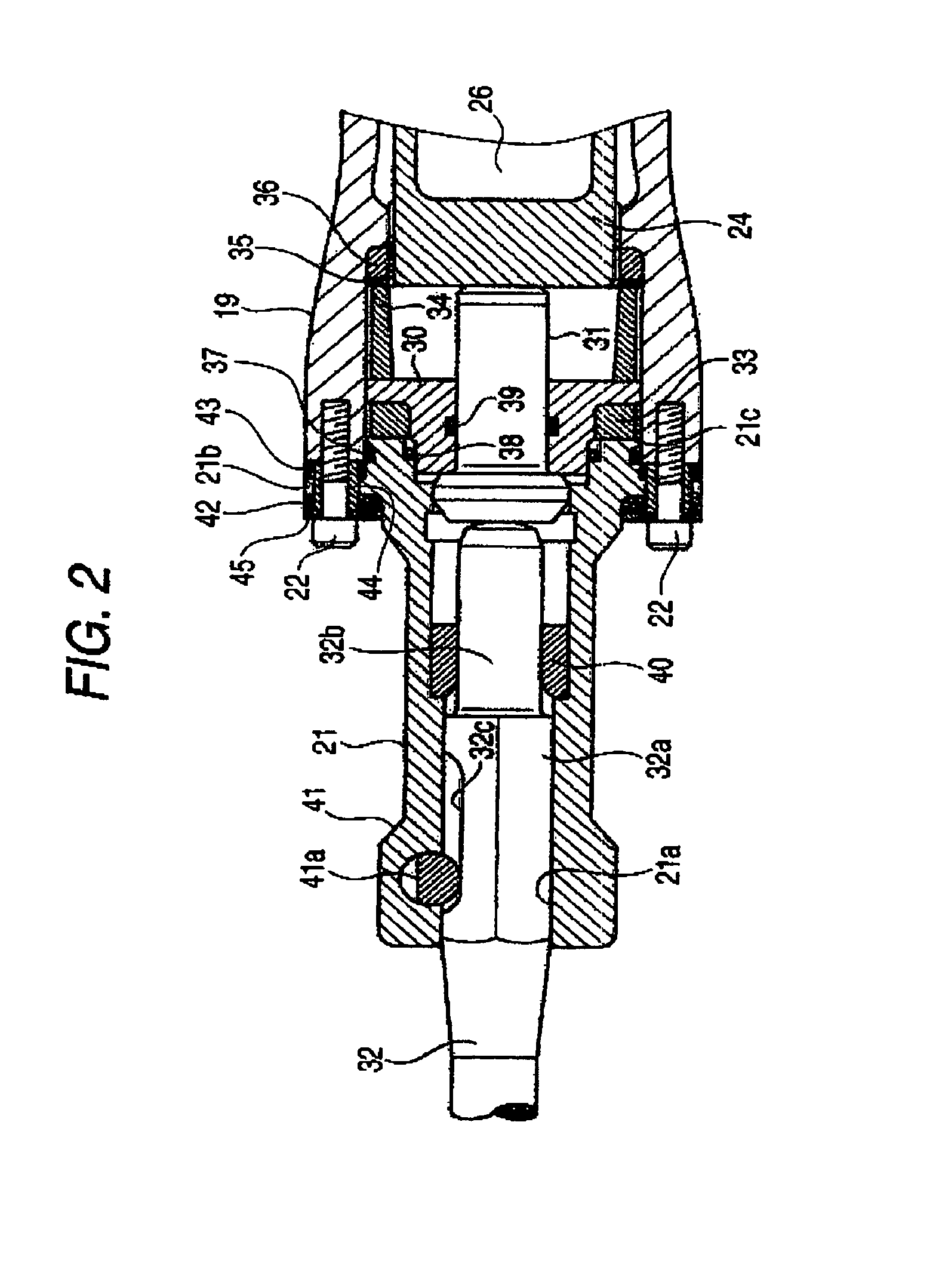
[0046]FIG. 1 is a partially-broken longitudinal sectional view of a striking tool, FIGS. 2 and 3 are longitudinal sectional diagrams of the tip end portion of the striking tool, FIG. 4 is a an enlarged diagram showing the details of a portion A in FIG. 3, and FIG. 5 is a partially sectional view showing the coupling structure of a portion B in FIG. 1.

[0047]In the striking tool 1, as shown in FIG. 1, a motor 2 serving as a driving source is housed and disposed in a transversal state within a casing 3. An output shaft 4 extending to the vertical direction of the motor 2 is supported at its upper and lower end portions by a pair of upper and lower bearings 5 so as to rotate freely, respectively. A pinion 6 is integrally provided at the upper end portion of the output shaft 4.

[0048]An inner cover 7 is attached to the upper portion of the casing 3. A gear cover 8 is attached to...


PUM

PropertyMeasurementUnit
air pressureaaaaaaaaaa
impact forceaaaaaaaaaa
inner diameteraaaaaaaaaa

Abstract

An impact force is transmitted to a tip end tool due to the changes of the air pressure within an air chamber generated by the reciprocal operation of the piston within a striker. The attachment portion of a tip end tool holding member for holding the tip end tool to a cylinder casing is sandwiched between buffers disposed in the two directions of the axial direction of the tool thereby to elastically support the tip end tool holding member to be movable in the two directions of the axial direction of the tool.

Description

BACKGROUND OF THE INVENTION[0001]1. Field of the Invention[0002]The present invention relates to a striking tool which performs various operations such as chipping, crushing of a member to be scraped such as concrete.[0003]2. Description of the Related Art[0004]A striking tool has been known which is driven by a motor and arranged to perform the various operations such as chipping, crushing of a member to be scraped such as concrete. An example of such a striking tool is shown in FIGS. 6 and 7.[0005]That is, FIG. 6 is a perspective view showing the external appearance of a conventional striking tool 101 and FIG. 7 is a partially-broken longitudinal sectional diagram of the striking tool 101. As shown in FIG. 7, in the striking tool 101, the rotation of a motor 102 housed within a motor casing 103 is transmitted to a crank shaft 114 by means of a pinion 106, a counter gear 117 and a final gear 118 within a gear cover 108, whereby the crank shaft 114 is driven and rotated. Then, the r...

Claims


Application Information

Patent Timeline
Patent Type & Authority Patents(United States)
IPC IPC(8): B25D9/00B25D11/12B25D17/11B25D17/08B25D17/24
CPCB25D17/11B25D17/24B25D2211/068B25D2216/0015Y10T279/17042B25D2250/051B25D2250/121B25D2250/361Y10T279/17102B25D2222/57
Inventor SATO, SHINICHIROSUZUURA, TSUKASAHIRAI, TAKAHIRO
Owner KOKI HLDG CO LTD
Why Eureka
Try Eureka