
Package filling plant, a packing device and method for grouping a packing formation of packages and containers, and a packing device and method for grouping a packing formation of packages and containers

a packing device and packaging technology, applied in the field of packaging filling plant, can solve the problems of limiting the type of potential packaging patterns that can be achieved, affecting the quality of packaging materials, so as to achieve the effect of adjusting the tension of at least one band

Active Publication Date: 2011-07-14
KHS GMBH
View PDF14 Cites 15 Cited by
  • Summary
  • Abstract
  • Description
  • Claims
  • Application Information

AI Technical Summary

Benefits of technology

[0010]An object of the present application is therefore to make available a packaging and grouping device which can be used to achieve the broadest possible spectrum of packing patterns and to minimize the likelihood of damage.SUMMARY
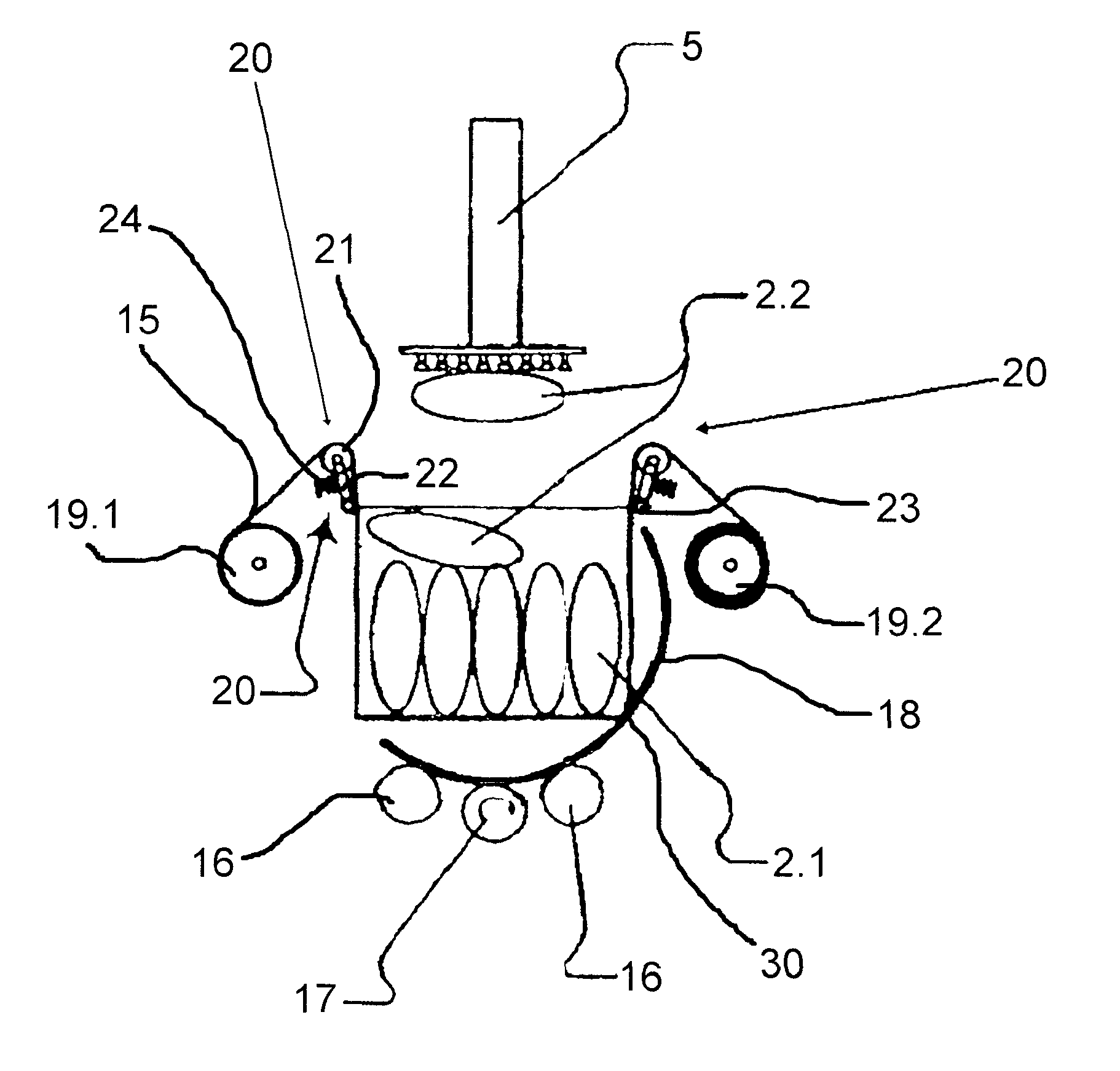
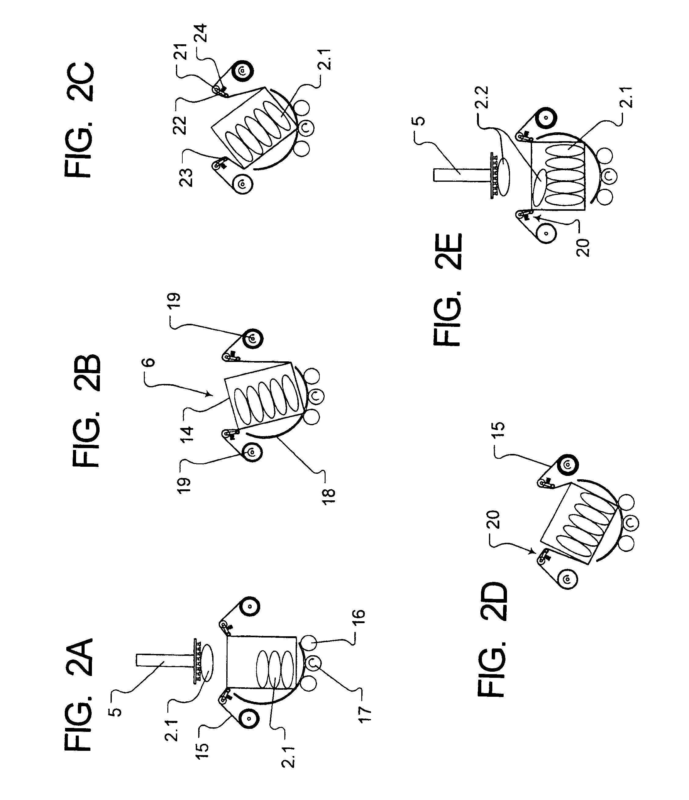
[0013]In at least one possible embodiment of the present application, the suitable lateral support of the packaging units that have already been inserted is always or substantially always essentially guaranteed or promoted, and that during rotation, the required and / or desired opening on the top is always or substantially always produced automatically, without having to move and vary large elements such as flaps or supports.
[0016]In one possible embodiment of the present application, the grouping can be done very loosely and then the desired density or pressure can be set without destabilizing the packing pattern. To achieve this variation in size or pressure with as little vibration or shaking as possible, it is possible to provide at least one motorized drive in the framework or base grid of the receptacle unit and to construct the base grid or base body so that it is telescoping at least in parts.
[0017]The bands are secured or fastened on at least one end outside the receptacle unit. In one possible embodiment of the present application, both ends of the band or the bands are secured. The bands thereby have a tensioning device on at least one end of the band. In one embodiment, the bands can be wound up on storage rolls or are mounted so that they are movable. This process is motor-driven. As a result of this arrangement, it is possible to accelerate the band back and forth simultaneously or substantially simultaneously with the rotational movement of the receptacle element, as a result of which the friction between the band surface on the one hand and between the receptacle element and the inserted packages on the other side is reduced.
[0019]For the further optimization of the path of the band and the band movement, at least one tensioning and guide element is provided which comprises a stationary base roll and a guide roll which is pivotably mounted on a lever arm, by means of which the at least one band or band-like element is guided. This guide roller or guide roll can be motor driven so that it can be moved at a right angle to the direction of the band in at least one direction. In this manner it is possible to always or substantially always close the receptacle unit optimally and to prevent, restrict, and / or minimize the packages that have been inserted from falling out.

Problems solved by technology

A device of this type severely limits the type of potential packaging patterns that can be achieved and cannot reliably prevent, restrict, and / or minimize the slipping of individual packaging units, for example those that are on top when the flaps are closed.
Sliding of the individual packages could then lead to excessive pressure on the contents and in the worst case could result in damage to the packaging unit itself.

Method used


Image

  • Package filling plant, a packing device and method for grouping a packing formation of packages and containers, and a packing device and method for grouping a packing formation of packages and containers
  • Package filling plant, a packing device and method for grouping a packing formation of packages and containers, and a packing device and method for grouping a packing formation of packages and containers
  • Package filling plant, a packing device and method for grouping a packing formation of packages and containers, and a packing device and method for grouping a packing formation of packages and containers

Examples


Embodiment Construction

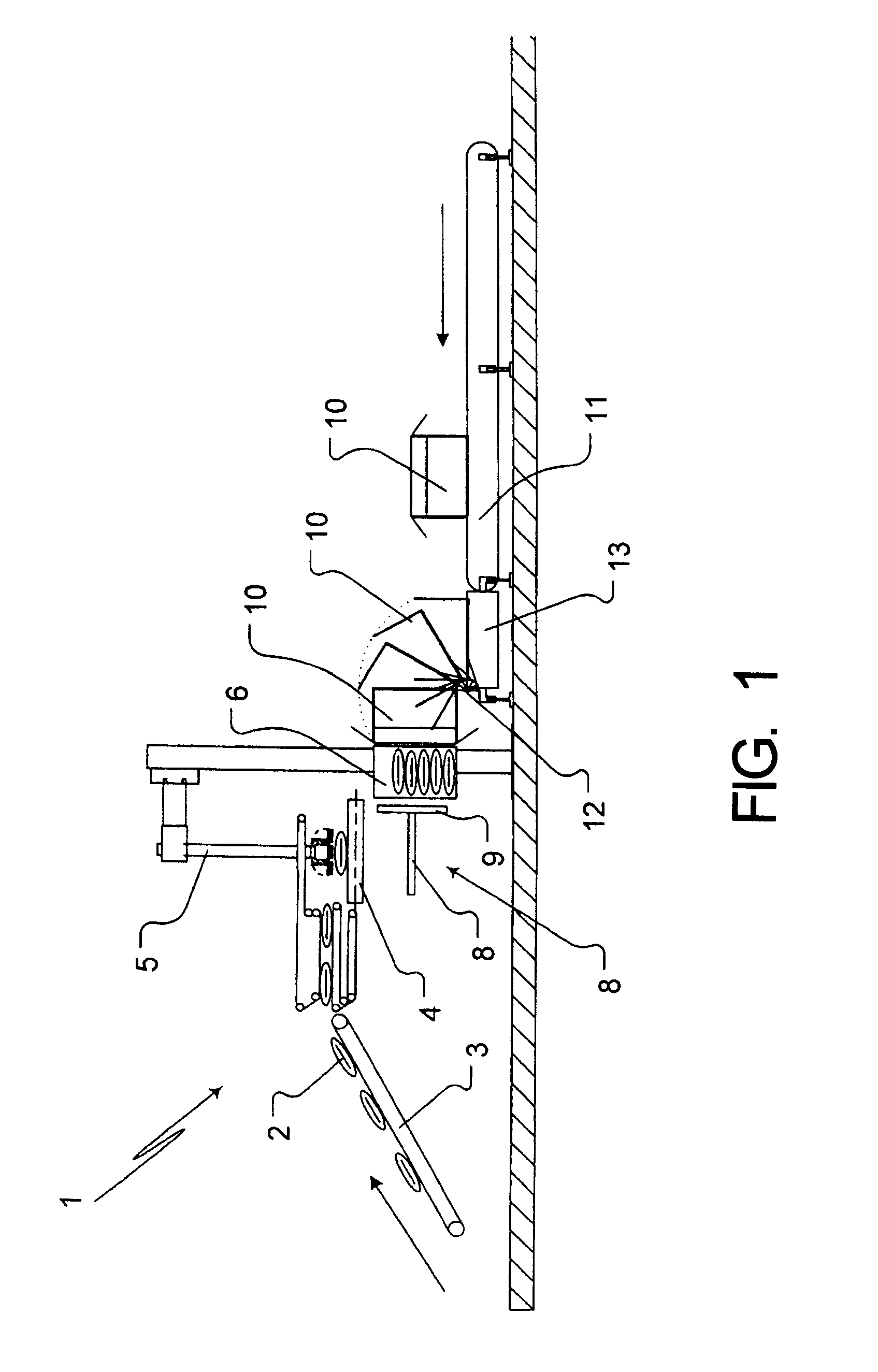
[0037]FIG. 1 shows the packing and grouping device 1 according to the present application in an overall view. The individual items or individual packaging units, which are referred to below as packaging units 2, are transported by means of a feed conveyor 3 to a pre-grouping unit 4. In the pre-grouping unit 4, a plurality of packaging units 2 are positioned in a single layer at the desired distance from one another and are then lifted by the vacuum gripper 5, which in this case is a robot with an articulated arm, and placed into the receptacle unit 6.

[0038]The details of the receptacle unit 6 are illustrated more clearly in FIG. 2. Facing the receptacle unit 6 is a pusher device 7 which comprises a push rod 8, a push plate 9 and a motor drive (not shown), which is used to insert the packing units 2 arranged in the final group into the open box 10.

[0039]The empty boxes 10 are moved by means of a conveyor belt 11 to a tipping device 12 and positioned opposite the receptacle unit 6. In...


PUM

PropertyMeasurementUnit
Angleaaaaaaaaaa
Angleaaaaaaaaaa
Sizeaaaaaaaaaa

Abstract

A package filling plant, a packing device and method for grouping a packing formation of packages and containers, and a packing device and method for grouping a packing formation of packages and containers. The abstract of the disclosure is submitted herewith as required by 37 C.F.R. §1.72(b). As stated in 37 C.F.R. §1.72(b): A brief abstract of the technical disclosure in the specification must commence on a separate sheet, preferably following the claims, under the heading “Abstract of the Disclosure.” The purpose of the abstract is to enable the Patent and Trademark Office and the public generally to determine quickly from a cursory inspection the nature and gist of the technical disclosure. The abstract shall not be used for interpreting the scope of the claims. Therefore, any statements made relating to the abstract are not intended to limit the claims in any manner and should not be interpreted as limiting the claims in any manner.

Description

CONTINUING APPLICATION DATA[0001]This application is a Continuation-In-Part application of International Patent Application No. PCT / EP2008 / 010159, filed on Dec. 1, 2008, which claims priority from Federal Republic of Germany Patent Application No. 10 2008 005 608.1, filed on Jan. 22, 2008. International Patent Application No. PCT / EP2008 / 010159 was pending as of the filing date of this application. The United States was an elected state in International Patent Application No. PCT / EP2008 / 010159.BACKGROUND[0002]1. Technical Field[0003]The present application relates to in a package filling plant, a packing device and method for grouping a packing formation of packages and containers, and a packing device and method for grouping a packing formation of packages and containers.[0004]2. Background Information[0005]Background information is for informational purposes only and does not necessarily admit that subsequently mentioned information and publications are prior art.[0006]Some package...

Claims


Application Information

Patent Timeline
IPC IPC(8): B65B5/10
CPCB65B5/061B65B35/50B65B5/108B65B5/106B65B35/56
Inventor TILL, VOLKERMATHEYKA, THOMAS
Owner KHS GMBH
Learn More