Magnetic tape and magnetic tape cartridge

a technology of magnetic tape and cartridge, which is applied in the direction of maintaining the alignment of the head carrier, magnetic materials for record carriers, instruments, etc., can solve the problems of reducing the output, increasing the error rate, and serious impact of the spacing between the magnetic layer and the magnetic head

Inactive Publication Date: 2006-08-15
MAXELL HLDG LTD
View PDF14 Cites 13 Cited by
  • Summary
  • Abstract
  • Description
  • Claims
  • Application Information

AI Technical Summary

Benefits of technology

[0017]The present invention is to overcome the foregoing problems, and a primary object of the present invention is to provide a magnetic tape, a PES from which i

Problems solved by technology

When the recording wavelength is shortened, the influence of spacing between the magnetic layer and the magnetic heads becomes serious.
Thus, if the magnetic layer has large projections or dents, which leads to a decrease in output due to spacing loss, the error rate increases.
The two-reel type cartridge has another problem in that the dimensions of the cartridge become larger and the memory capacity per volume becomes smaller.
However, this problem is solved by employing the above servo system: that is, even if the position of the magnetic tape very slightly fluctuates in the widthwise direction, the entire magnetic head array moves in the tape widthwise direction in association with such a fluctuation, so that the recording-reproducing head can always reach a correct data track.
Further, when the recording track width is as narrow as 21 μm or less, it is confirmed that not only th

Method used


Image

  • Magnetic tape and magnetic tape cartridge
  • Magnetic tape and magnetic tape cartridge
  • Magnetic tape and magnetic tape cartridge

Examples


example 1

[0118]

(1)Iron oxide powder (particle size: 0.11 × 0.02 μm) 68 partsα-Alumina (particle size: 0.07 μm)  8 partsCarbon black (particle size: 25 nm; 24 partsoil absorption: 55 g / cc)Stearic acid2.0 partsVinyl chloride-hydroxypropyl acrylate copolymer8.8 parts(—SO3Na group content: 0.7 × 10⁻⁴ eq. / g)Polyesterpoyurethane resin4.4 parts(Tg: 40° C., —SO3Na group content: 1 × 10⁻⁴ eq. / g)Cyclohexanone 25 partsMethyl ethyl ketone 40 partsToluene 10 parts(2)Butyl stearate  1 partCyclohexanone 70 partsMethyl ethyl ketone 50 partsToluene 20 parts(3)Polyisocyanate4.4 parts(Colonate L manufactured by Nippon Polyurethane)Cyclohexanone 10 partsMethyl ethyl ketone 15 partsToluene 10 parts

[0119]

(1)Ferromagnetic iron metal powder 100 parts(Co / Fe: 20 atomic %, Y / (Fe + Co): 3 atomic %,Al / (Fe + Co): 5 wt. %, Ca / Fe: 0 wt. %;σs: 155 A · m2 / kg, Hc: 149.6 kA / m, pH: 9.4,major axis length: 0.10 μm)Vinyl chloride-hydroxypropyl acrylate copolymer12.3 parts(—SO3Na group content: 0.7 × 10⁻⁴ eq. / g)Polyesterpoyurethane...

examples 2 to 13

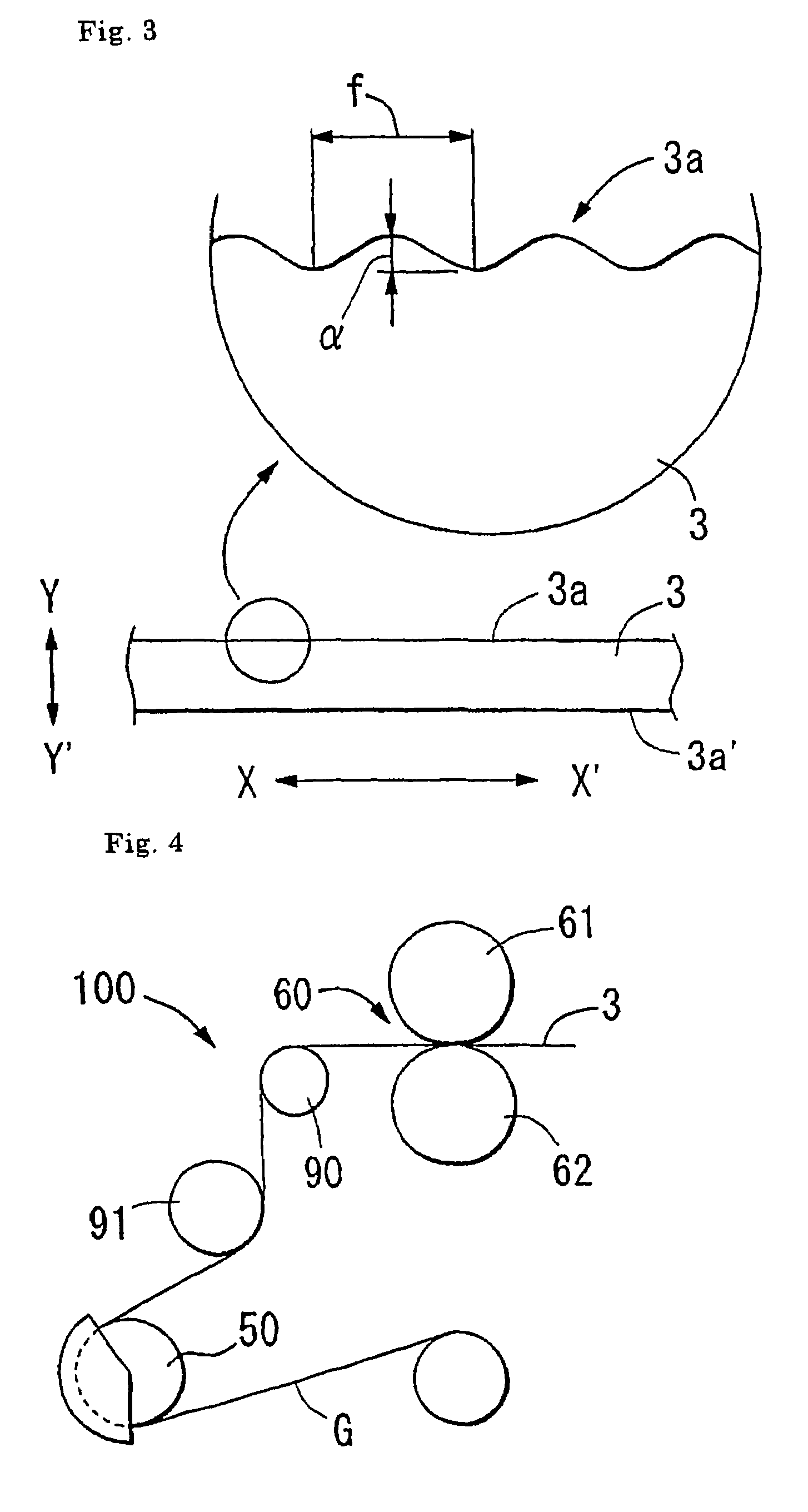
[0135]Magnetic tape cartridges for computers of Examples 2 to 13 were constructed in the same manner as in Example 1, except that a part of the conditions were changed to the conditions indicated in Tables 2 or 3. The term, “direct drive” as seen below means the motor's direct driving of the cutter-driving section without using any power-transmitting device using a belt, in order to prevent the occurrence of edge weave due to the vibration of the drive belt.

examples 14 to 17

[0137]Magnetic tape cartridges for computers of Examples 14 to 17 were constructed in the same manner as in Example 1, except that the reels shown in Table 5 were used.


PUM


Abstract

A magnetic tape which is run at a speed of 4 m/sec. or higher and has recording tracks with a width of 21 μm or less, and which includes a non-magnetic support, at least one magnetic layer formed on one surface of the non-magnetic support, and a backcoat layer formed on the other surface of the non-magnetic support, wherein servo signals for controlling tracking are recorded on the magnetic layer or the backcoat layer, the value of (α/W) X (V/f) is 10 [s−1] or less, and/or the value of (α/W) is 0.1 or less, wherein V [mm/sec.] is the tape-running speed; α [μm] is an amount of a weave with a cycle of f [mm] on one edge of the tape or the other edge thereof, as the reference side, for the running of the tape; and W [μm] is a width of the recording track. The magnetic tape can decrease PES and off-track and thus is excellent in servo tracking performance.

Description

TECHNICAL FIELD[0001]This application is the national phase under 35 U.S.C. §371 of PCT International Application No. PCT / JP02 / 02280 which has an International filing date of Mar. 12, 2002, which designated the United States of America.[0002]The present invention relates to a magnetic tape cartridge having a large recording capacity, a high access speed and a high transfer speed. In particular, the present invention relates to a single reel type magnetic tape cartridge suitable for data-backup, including a magnetic tape which records magnetic signals or optical signals for servo tracking, and reproduces magnetically recorded signals with reproducing heads containing magnetoresistance elements (hereinafter referred to as “MR head”).BACKGROUND ART[0003]Magnetic tapes have found various applications in audio tapes, videotapes, computer tapes, etc. In particular, in the field of magnetic tapes for data-backup (or backup tapes), tapes having memory capacities of several tens GB or more p...

Claims


Application Information

Patent Timeline
IPC IPC(8): G11B5/584G11B5/73G11B5/70G11B5/735G11B5/738G11B5/78G11B23/107
CPCG11B5/584G11B23/107G11B5/70
Inventor NAKAMURA, AKIHIROTANI, MASAKAZUAMANO, KOUSUKEARAKAWA, SHINJISHIMIZU, JYUNICHI
Owner MAXELL HLDG LTD
Why Eureka
Try Eureka