Pivoting/telescoping winch boom for a brush chipper and method of using same

a technology of telescopic winch and chipper, which is applied in the direction of hoisting equipment, grain treatment, manufacturing tools, etc., can solve the problems of not lifting the branches up, and achieve the effect of facilitating choking and great ease of manipulating the material

Active Publication Date: 2010-10-26
VERMEER MFG CO
View PDF15 Cites 17 Cited by
  • Summary
  • Abstract
  • Description
  • Claims
  • Application Information

AI Technical Summary

Benefits of technology

[0010]The present invention relates to a brush chipper having a pivoting and or reciprocating winch. Pivoting the winch up gets it out of the way, especially of small branches attached to larger limbs and logs being fed into the feed rollers. This prevents the rope from being snagged and allows less restricted feeding.
[0011]Earlier prior art fixed winches would be considered the boom-down position. The boom-up position allows for easier maintenance work. When a maintenance worker may have to work from the feed table, the boom is entirely out of the way.
[0012]With the pivoting winch, lighter material can be dragged to the machine in the boom-down position and then can be quickly and easily lifted to the feed table using the pivoting action. Greater locating possibilities are allowed with the pivoting winch. The pivoting boom could be set in the boom-up position while the log was attached to the rope to the side of the machine.
[0014]Another embodiment of the pivoting winch boom which has been considered is that of a telescoping function. This would include another tube inside of the boom which could be extended by a hydraulic cylinder to extend the boom pulley to a greater distance from the machine. This embodiment would allow further location possibilities and greater ease of manipulating the material to the ground.
[0015]In an alternative embodiment in which the pivot point would be moved to a position behind the winch and closer to the ground, a longer boom would enable it to reach greater distances thereby allowing the boom to be used to carry the log for a greater distance. The boom would also be able to pivot down closer to the log possibly allowing easier choking and may eliminate the occasional inconvenience of re-choking the log during retrieval. A fixed winch, because of the upward angle chosen for most purposes, sometimes requires additional re-choking of the attachment to the log.

Problems solved by technology

For instance, a log lying in a ditch to the side of the machine may need to be approached from a steep angle which is not possible with a fixed winch.
For lighter materials such as small branches, previous fixed-boom models had a problem with the branches not lifting up to the feed table like heavier logs do.

Method used


Image

  • Pivoting/telescoping winch boom for a brush chipper and method of using same
  • Pivoting/telescoping winch boom for a brush chipper and method of using same
  • Pivoting/telescoping winch boom for a brush chipper and method of using same

Examples


Embodiment Construction

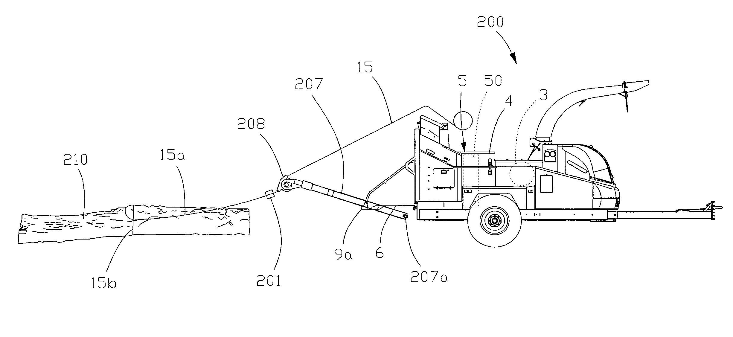
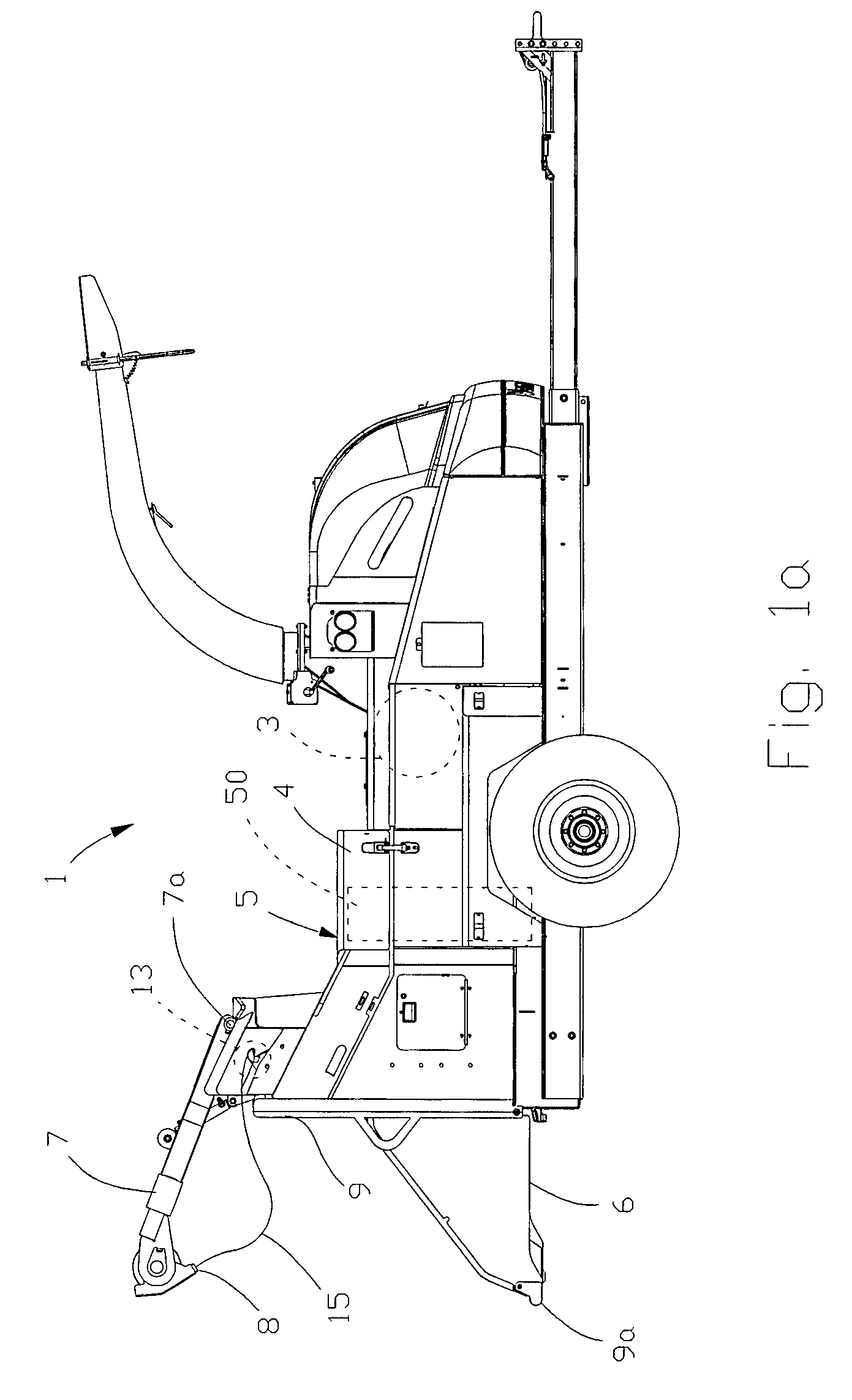
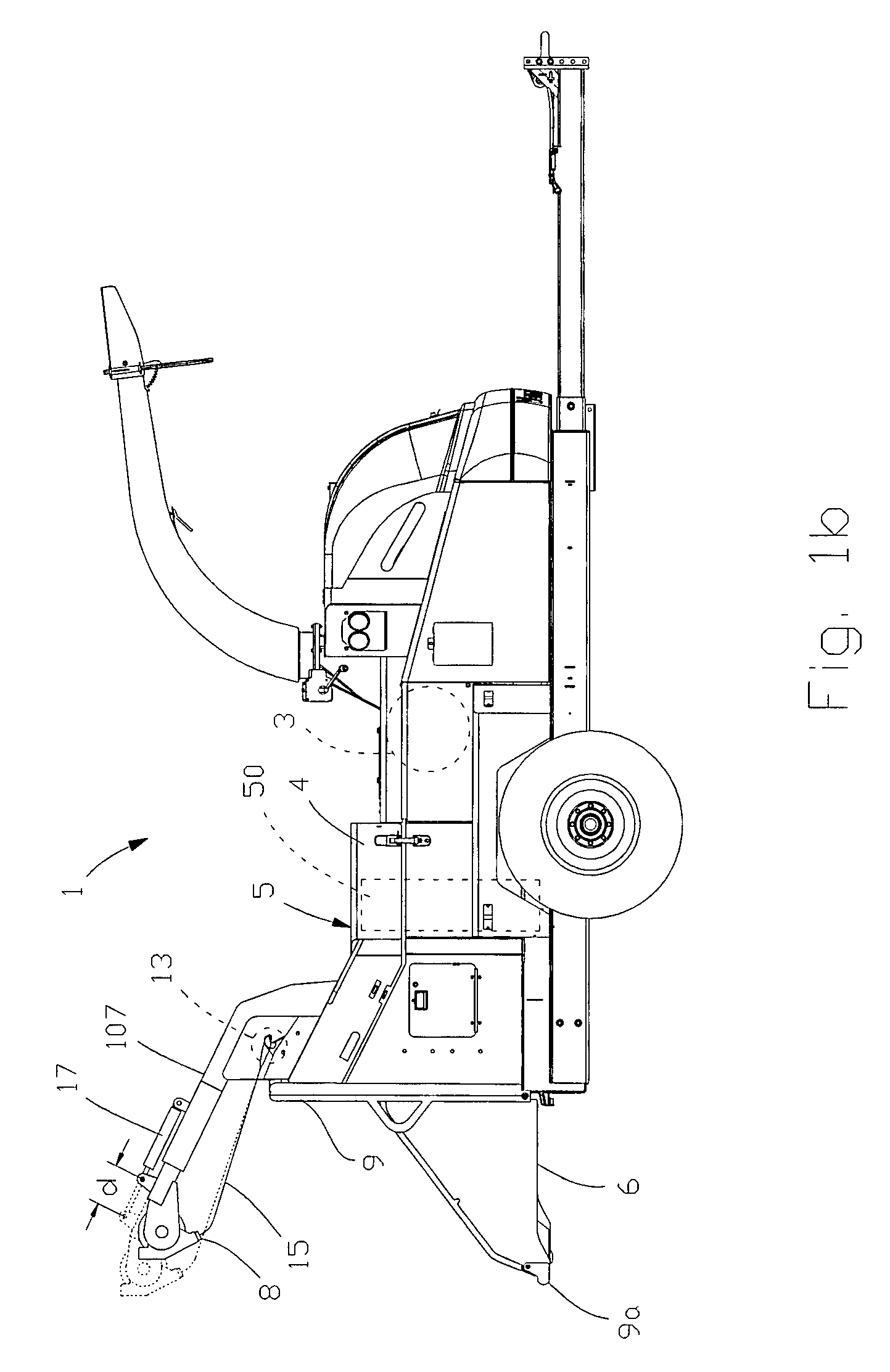
[0031]Referring now to the drawings wherein like reference numerals indicate identical or corresponding parts throughout the several views, FIG. 1 shows a brush chipper 1 constructed in accordance with the present invention. This chipper can be constructed generally in accordance with U.S. patent application Ser. No. 11 / 756,321, which is incorporated herein in its entirety.

[0032]FIG. 1 illustrates a wood chipper 1 constructed in accordance with the principles of the present invention. The wood chipper 1 includes a frame (e.g., a trailer structure), a cutter housing supported on the frame with a cutter mechanism 3 positioned within the cutter housing. A feed housing 4 is also supported on the frame. The feed housing encloses a feed mechanism 5 adapted for feeding a log into the cutter mechanism 3. The feed housing 4 is located between the cutter mechanism 3 and a feed table 6 that extends outward from the feed housing 4. The feed table 6 is elevated above ground level and is position...


PUM

PropertyMeasurementUnit
reach distanceaaaaaaaaaa
distanceaaaaaaaaaa
axis of rotationaaaaaaaaaa

Abstract

A brush chipper is disclosed having a pivoting and / or reciprocating winch for improving the efficiency of the winch.

Description

CROSS REFERENCE TO RELATED APPLICATIONS[0001]Not Applicable.STATEMENT REGARDING FEDERALLY SPONSORED RESEARCH OR DEVELOPMENT[0002]Not Applicable.REFERENCE TO MICROFICHE APPENDIX[0003]Not Applicable.BACKGROUND OF THE INVENTION[0004]1. Field of the Invention[0005]The present invention relates generally to a winch boom for a brush chipper and more particularly to a pivoting / telescoping winch boom for a brush chipper.[0006]2. Background Art[0007]Sometimes small branches on a larger limb can catch on a fixed winch as the larger limb is fed into the brush chipper. At other times, a fixed winch is in the way during routine maintenance of a feed table on a brush chipper. For instance, a log lying in a ditch to the side of the machine may need to be approached from a steep angle which is not possible with a fixed winch.[0008]For lighter materials such as small branches, previous fixed-boom models had a problem with the branches not lifting up to the feed table like heavier logs do.[0009]Accor...

Claims


Application Information

Patent Timeline
Patent Type & Authority Patents(United States)
IPC IPC(8): B02C19/00
CPCA01G3/002B02C18/2225
Inventor BOUWERS, JOHN T. B.O'HALLORAN, JAMES L.REMPE, SCOTT A.
Owner VERMEER MFG CO
Why Eureka
Try Eureka