Energy recovery and reuse methods for a hydraulic system

a hydraulic system and energy recovery technology, applied in the field of hydraulic systems, can solve the problems of inability to use recovered fluid, inability to store fluid, and difficulty in achieving effective operation

Inactive Publication Date: 2010-11-02
HUSCO INT INC
View PDF10 Cites 44 Cited by
  • Summary
  • Abstract
  • Description
  • Claims
  • Application Information

AI Technical Summary

Problems solved by technology

In this situation, the fluid is exhausted from the cylinder under relatively high pressure, thereby containing energy that normally is lost when the pressure is metered through the valve assembly.
However, a challenge to efficient energy recovery and reuse is that the stored hydraulic fluid has to be at the proper pressure and volume to power an actuator.
For example, if the external force acting on the cylinder assembly is insufficient to pressurized the exhausting fluid above the level of pressure in the accumulator, then that fluid cannot be stored.
For example, if the load on the hydraulic actuator requires a greater pressure than the accumulator pressure, then the recovered fluid cannot be employed.
Also if the hydraulic actuator needs to move so far as to require a greater volume of fluid than is stored in the accumulator, effective operation may be difficult to achieve.
Another limiting factor is that as the hydraulic actuator consumes fluid from the accumulator, the accumulator pressure decreases reducing the ability of the remaining fluid to power the actuator.

Method used


Image

  • Energy recovery and reuse methods for a hydraulic system
  • Energy recovery and reuse methods for a hydraulic system
  • Energy recovery and reuse methods for a hydraulic system

Examples


example 1

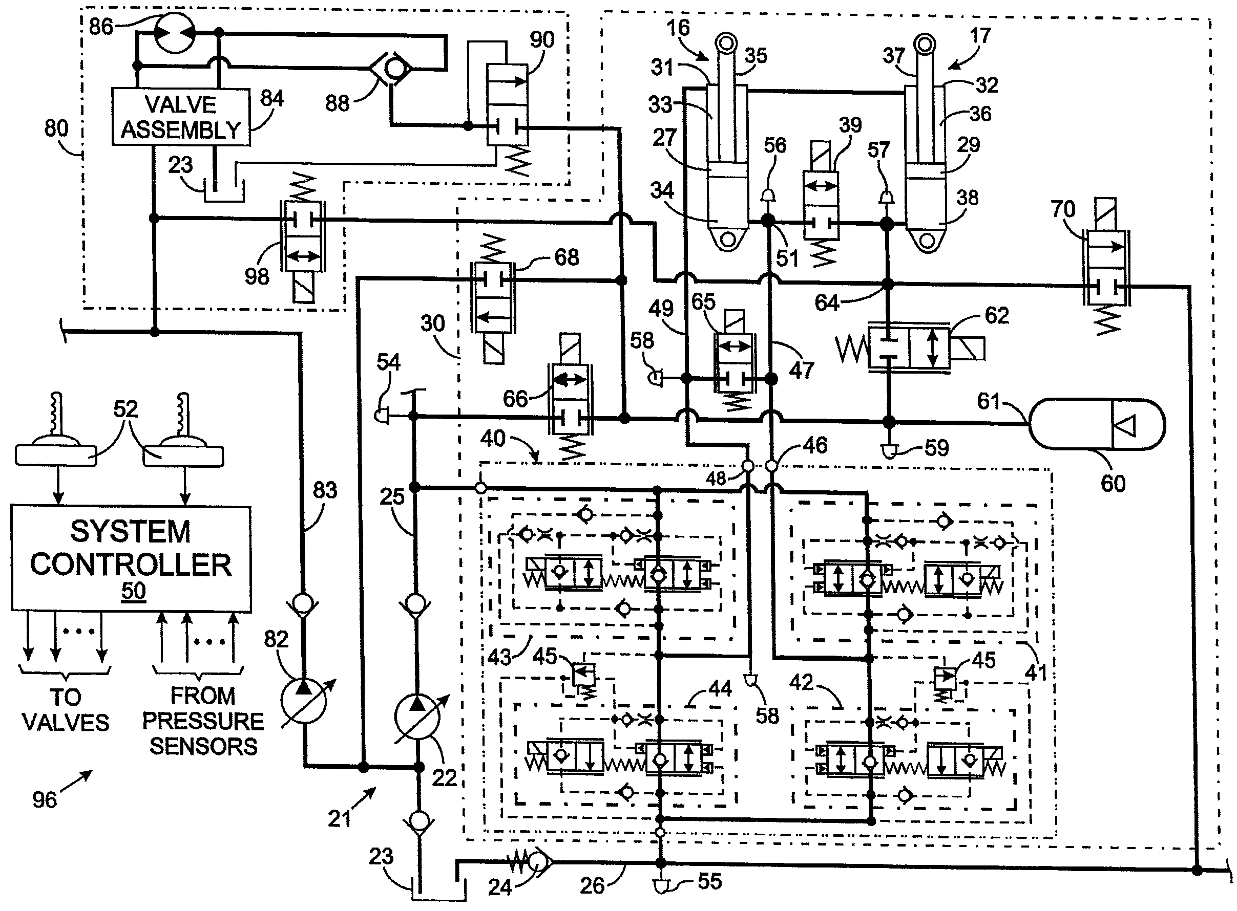
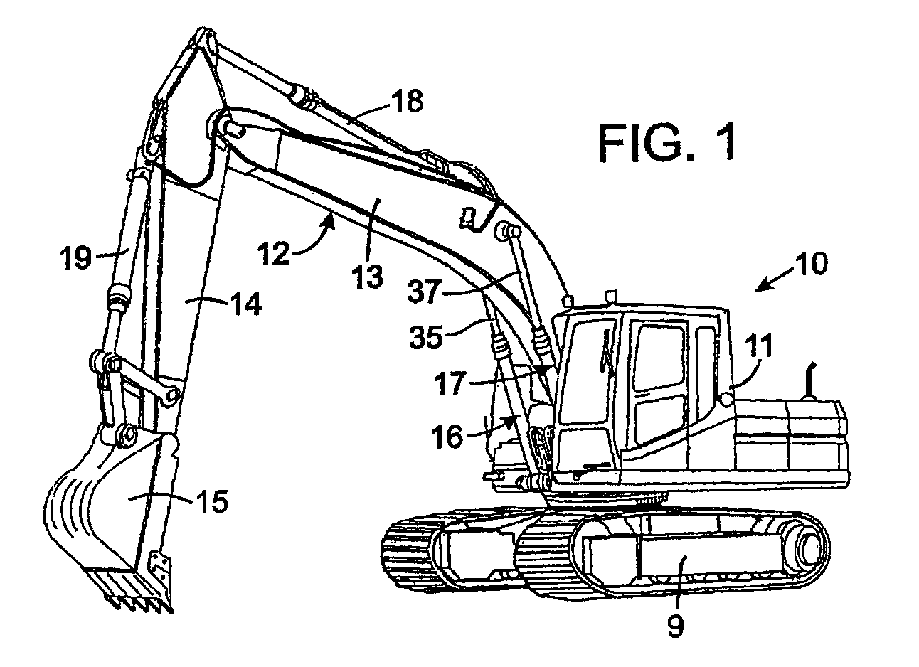
[0042]Assume that the first pump 22 supplies fluid to other hydraulic functions on the machine and is running at 300 bar pressure to satisfy the highest demand of those functions. In addition, assume that still other hydraulic functions are connected to the second pump 82, which is running at 200 bar pressure to satisfy its highest fluid demand. Further assume that 250 bar pressure is required to lift the load on the boom 13.

[0043]With a conventional system, the first pump 22 would stay at 300 bar and the extra 50 bar would be “burned” as pressure compensation losses. In that conventional system, the pressure of the second pump 82 would rise to 250 bar and its other hydraulic functions would produce pressure compensation losses, due to the pressure being greater than required at those functions.

[0044]With the system shown in FIG. 3, the first pump 22 continues operating at 300 bar and the second pump 82 continues to operate at 200 bar, thus a combined average of 250 bar. Each of tho...

example 2

[0045]Assume that there is another hydraulic function connected to the first pump 22 that already has consumed all that pump's output flow. If raising the boom 13 is commanded, then the second pump 82 can furnish all the power to the boom through supply control valve 98 and the second cylinder assembly 17, while fluid for the head chamber 34 of first cylinder 31 is drawn from the return conduit 26 through the anti-cavitation check valve in the second EHP control valve 42.

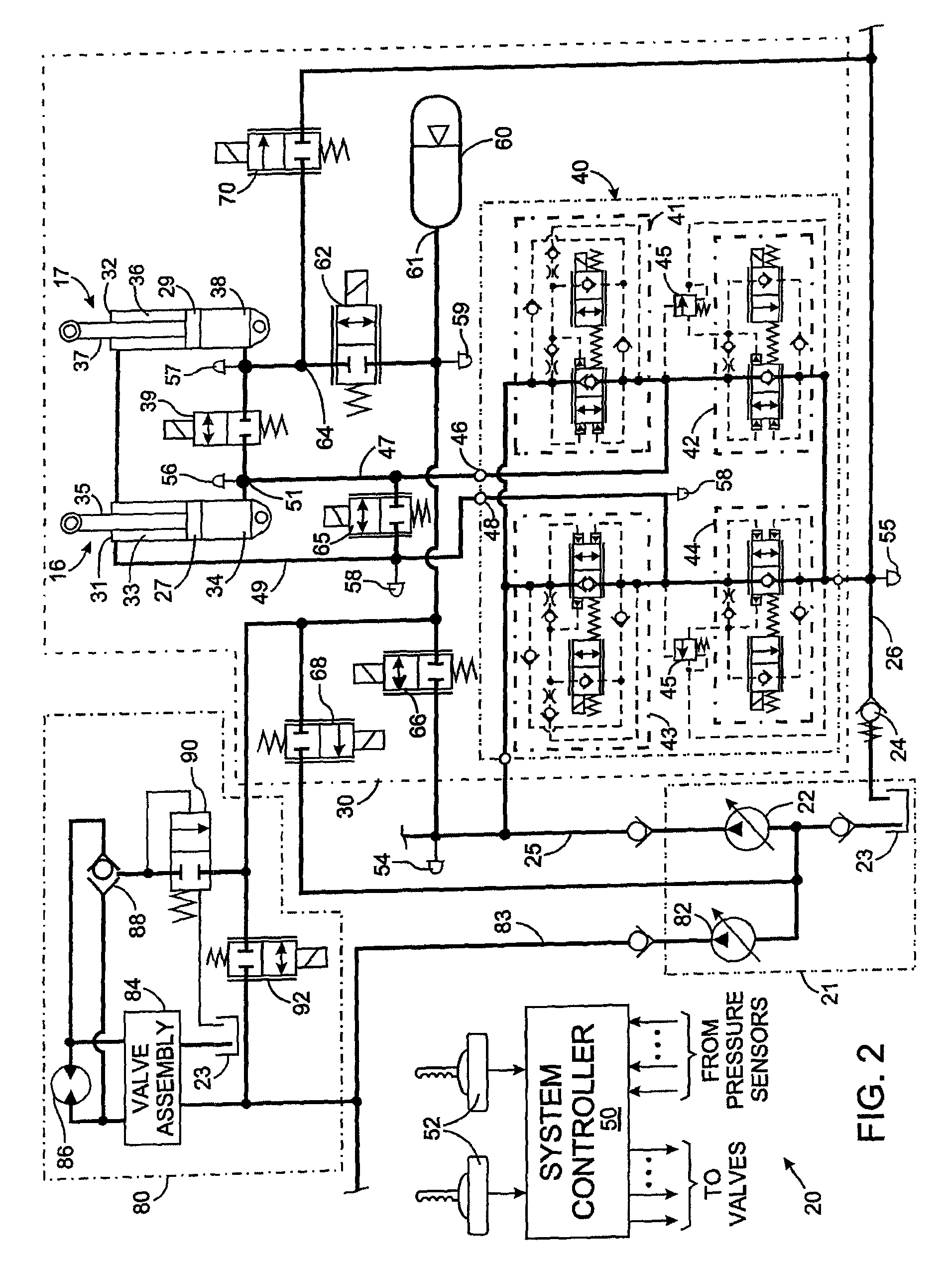
[0046]The functionality of examples 1 and 2 can be provided by a third hydraulic system 100 that uses solenoid operated spool valves, such as depicted in FIG. 4. Hydraulic system 100 includes a boom function 102 in which the same components as in the previously described systems have been identified with identical reference numerals. The head chambers 34 and 38 of the first and second boom cylinders 31 and 32 are coupled hydraulically by a bidirectional, electrohydraulic cylinder separation control valve 39. An elec...


PUM


Abstract

A method provides several modes for recovering hydraulic energy produced by an overrunning load acting on cylinders connected in parallel to a machine component. In one mode, fluid from first chambers in both cylinders is routed into the accumulator, while other fluid is directed into second chambers of those cylinders. In a different mode, fluid is routed from the first chamber of only one cylinder into the accumulator, and fluid from the first chamber of the other cylinder goes into the second chambers of both cylinders. Yet another mode comprises routing fluid from the first chambers of both cylinders into the second chambers of both cylinders. In still another mode, fluid from the first chambers of both cylinders goes into the return conduit while the second chambers of both cylinders receive fluid from a supply conduit. Several modes of reusing the recovered energy are described.

Description

CROSS-REFERENCE TO RELATED APPLICATIONS[0001]This application claims benefit of U.S. Provisional Patent Application No. 60 / 865,710 filed on Nov. 14, 2006 and U.S. Provisional Patent Application No. 60 / 913,457 filed on Apr. 23, 2007.STATEMENT REGARDING FEDERALLY SPONSORED RESEARCH OR DEVELOPMENT[0002]Not ApplicableBACKGROUND OF THE INVENTION[0003]1. Field of the Invention[0004]The present invention relates to hydraulic systems that control fluid flow to a hydraulic actuator which moves a mechanical component on a machine, and in particular to recovering energy from the hydraulic actuator and utilizing the recovered energy subsequently to power the hydraulic actuator.[0005]2. Description of the Related Art[0006]Construction and agricultural equipment employ hydraulic systems to operate different mechanical elements. For example, an excavator is a common construction machine that has boom pivotally coupled at one end to a tractor and having a bucket at the other end for scooping dirt a...

Claims


Application Information

Patent Timeline
Patent Type & Authority Patents(United States)
IPC IPC(8): F16D31/02
CPCE02F9/2217E02F9/2228E02F9/2292E02F9/2296F15B11/006F15B11/024F15B21/14F15B2211/212F15B2211/30575F15B2211/625F15B2211/6313F15B2211/6346F15B2211/7053F15B2211/7058F15B2211/7128F15B2211/88
Inventor HAMKINS, ERIC P.STEPHENSON, DWIGHT B.PFAFF, JOSEPH L.TABOR, KEITH A.
Owner HUSCO INT INC
Why Eureka
Try Eureka