Methods and systems for calibrating for gain and phase imbalance and local oscillator feed-through

a local oscillator and gain and phase imbalance technology, applied in the field of transmitter calibration, can solve problems such as unwanted signals, affecting the accuracy of the signal, so as to reduce the gain and phase imbalance and reduce the feed-through of the local oscillator

Inactive Publication Date: 2010-11-09
AVAGO TECH INT SALES PTE LTD
View PDF5 Cites 39 Cited by
  • Summary
  • Abstract
  • Description
  • Claims
  • Application Information

AI Technical Summary

Benefits of technology

[0007]The present invention is directed to methods and systems to reduce gain and phase imbalances, and to reduce local oscillator feed-through.
[0008]In an embodiment, a method of calibrating a transmitter includes generating a test tone, frequency up-converting the test tone, monitoring one or more features of the up-converted test tone, and calibrating the transmitter in response to the monitoring, thereby reducing gain and phase imbalances and local oscillator feed-through.

Problems solved by technology

In other words, when a signal passes though the transmit chain, and the chain is unbalanced, an image is created.
In fact, while “intra-signal” imaging may be necessary for signal integrity, protecting the adjacent channel may be a regulatory issue.
LOFT can also be problematic on the receiver (e.g., during synchronization) when there is an unwanted LOFT component in the incoming signal that may lead to early triggering.
Both effects are desired to be suppressed, because both lead to unwanted signal at RF.
LOFT can cause saturation of analog blocks.
That is, the chain will be more prone to clipping or non-linear distortion.
Thus, before the mutual cancellation takes place, DC compensation tends to consume dynamic range.
One drawback of this approach is that the down-conversing circuitry can be an additional source of I / Q imbalance and LOFT / DC offset.
But this will increase the cost of the system beyond what is commercially practicable for many applications.
When there is I / Q imbalance and / or LOFT, however, the test tone and the unwanted frequency components will cause a “beating” effect on the RF envelope.
But in reality, a perfect downconverter would be prohibitively expensive to build.
A less than perfect system would inject its own DC offsets and would have its own impact on IQ imbalance.
As a result, it would be difficult to distinguish between transmitter imbalance and receiver imbalance.
This is because, when LOFT is eliminated or substantially eliminated, the even harmonics in the envelope beating will be entirely caused by IQ imbalance.
This procedure however, requires very sensitive power measurement circuitry, which may be hard to achieve especially when accurate LOFT compensation is needed.
Saturation is a non-linear distortion which leads to a loss in integrity on the monitored envelope signal.
This is generally a relatively coarse adjustment because the analog injections tend not to be as accurate as digital injections (i.e., di and dq).
Therefore, any remaining second harmonic beating is due primarily to I / Q imbalance.

Method used


Image

  • Methods and systems for calibrating for gain and phase imbalance and local oscillator feed-through
  • Methods and systems for calibrating for gain and phase imbalance and local oscillator feed-through
  • Methods and systems for calibrating for gain and phase imbalance and local oscillator feed-through

Examples


example embodiments

IV. EXAMPLE EMBODIMENTS

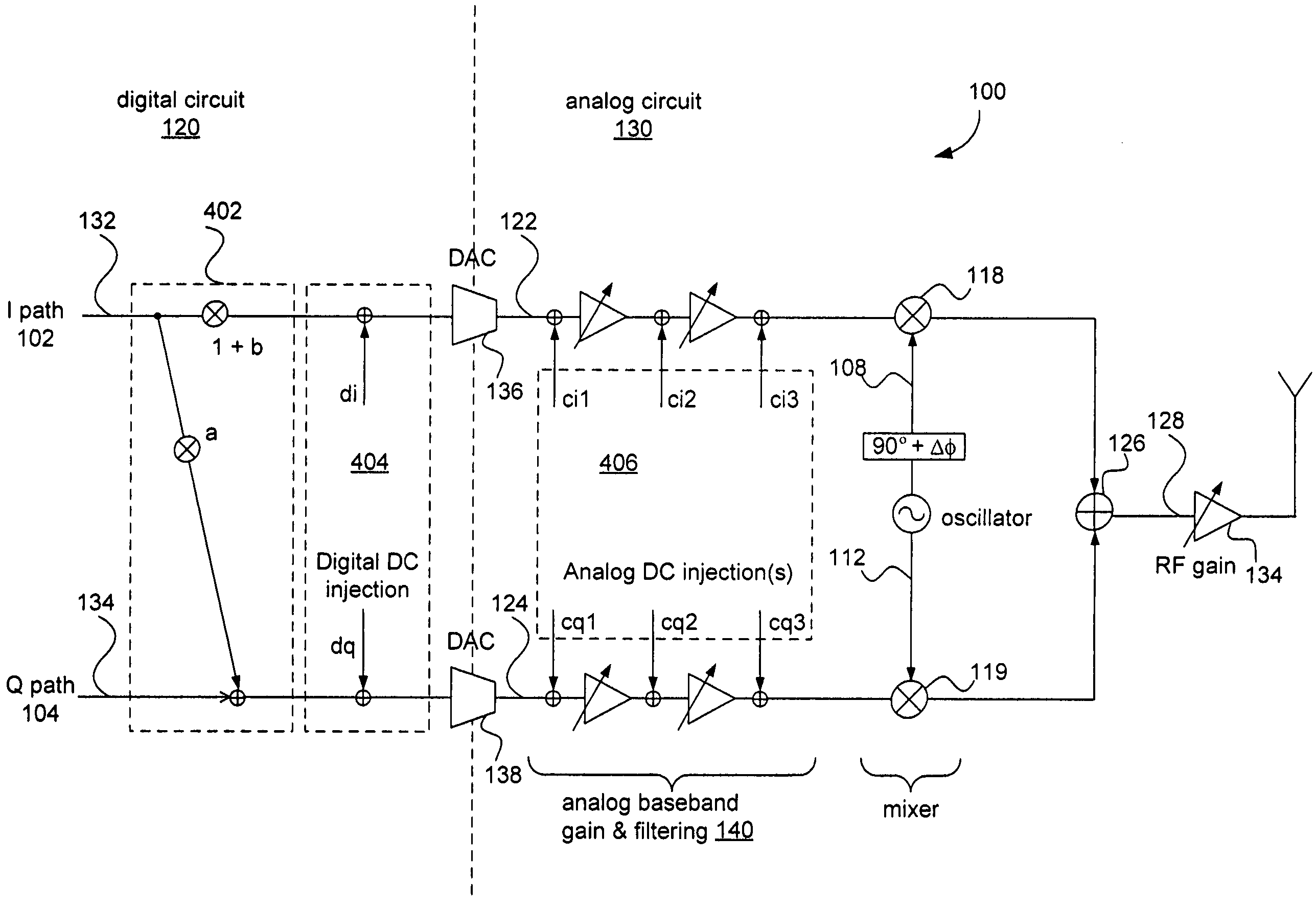
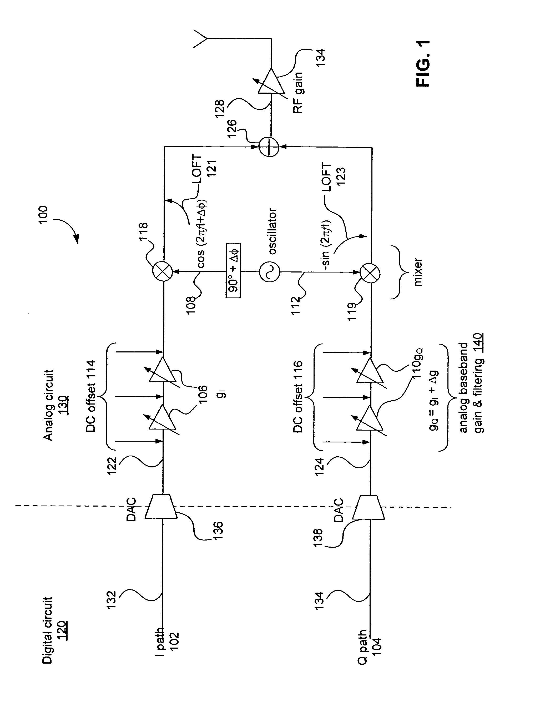
[0114]FIG. 11 is a more detailed block diagram of the transmitter 100 illustrated in FIG. 5. For ease of illustration, separate I and Q paths are not illustrated in FIG. 11. The discussion of FIG. 11 begins with the testtone generator 105.

[0115]The test tone generator 501 generates a pure complex test tone in the digital domain, seq_fT. In the example of FIG. 11, the test tone generator 501 is illustrated as a sample play buffer. As described above, the sample play buffer includes a storage medium that holds samples of a complex sinusoid. The samples encompass an integral number of test tone periods. During calibration, the samples are played repeatedly into the transmitter 100. This is illustrated in FIG. 11 as testtone signal seq_fT. An input multiplexer 1106 is controlled to pass the transmit signal 1102 during normal operation, or the test tone signal seq_fT during calibration.

[0116]In the example of FIG. 11, the test tone generator 501 also outputs a seco...


PUM


Abstract

Methods and systems to calibrating a transmitter for I / Q imbalance and local oscillator feed-through include generating a test tone, frequency up-converting the test tone, monitoring one or more features of the up-converted test tone, and adjusting one or more features of the transmitter in response to the monitoring. The monitoring optionally includes monitoring a beating of the envelope of the up-converted test tone. In an embodiment, a first harmonic of the up-converted test tone is monitored for local oscillator feed-through (LOFT). Alternatively, baseband data inputs to the transmitter are disabled, and LOFT is measured by measuring power at the transmitter output. A second harmonic of the up-converted test tone is monitored for gain and phase imbalances. The adjusting optionally includes adjusting a gain imbalance, adjusting a phase imbalance, and / or adjusting DC offsets. The adjusting optionally includes an iterative refinement process. Such a refinement process optionally includes performing a first monitoring, applying a set of relatively coarse settings to the one or more features in the transmitter, monitoring the beating resulting from each of the coarse settings, selecting the coarse setting corresponding the smallest beating, applying a set of relatively fine settings centered around the selected coarse setting, wherein the fine settings are more closely related to one another than are the coarse settings, monitoring the beating resulting from each of the fine settings, and selecting the fine setting corresponding the smallest beating.

Description

CROSS-REFERENCE TO RELATED APPLICATIONS[0001]This application claims the benefit of U.S. Provisional Application No. 60 / 702,324, filed Jul. 26, 2005, titled, “Methods and Systems for Calibrating for Gain and Phase Imbalance and Local Oscillator Feed-Through,” incorporated herein by reference in its entirety.BACKGROUND OF THE INVENTION[0002]1. Field of the Invention[0003]The invention relates to transmitter calibration and, more particularly, to gain and phase imbalance and local oscillator feed-through compensation.[0004]2. Related Art[0005]Transmitters that utilize in-phase and quadrature (“I and Q”) channels typically suffer from amplitude (i.e., gain) and phase imbalances, and from local oscillator feed-through (LOFT).[0006]What are needed therefore are methods and systems to reduce gain and phase imbalances, and to reduce local oscillator feed-through.SUMMARY OF THE INVENTION[0007]The present invention is directed to methods and systems to reduce gain and phase imbalances, and t...

Claims


Application Information

Patent Timeline
Patent Type & Authority Patents(United States)
IPC IPC(8): H04B1/04
CPCH04B17/21
Inventor HAMMERSCHMIDT, JOACHIMMOORTI, RAJENDRA T.
Owner AVAGO TECH INT SALES PTE LTD
Why Eureka
Try Eureka