Mandible positioning devices

a technology for positioning devices and mandibles, which is applied in the field of mandible positioning devices, can solve the problems of not being accessible, not allowing the adjustment of the spacing between the upper and lower bite blocks, and waking patients by the consequent lack of oxygen and blood

Active Publication Date: 2010-11-16
PHILIPS RS NORTH AMERICA LLC
View PDF15 Cites 55 Cited by
  • Summary
  • Abstract
  • Description
  • Claims
  • Application Information

AI Technical Summary

Benefits of technology

[0012]It is accordingly an object of the present invention to provide a novel and improved mandible positioning device having upper and lower bite blocks which can be manually adjusted in position relative to one another while the device is installed in the mouth of a patient.
[0013]It is a further object of the present invention to provide a manually adjustable mandible positioning device which allows a lower bite block to be adjusted forwardly relative to an upper bite block and which also allows the vertical spacing between the upper and lower bite blocks to be adjusted.
[0014]According to the present invention, there is provided a mandible positioning device comprising upper and lower bite blocks and a manually adjustable connection interconnecting the upper and lower bite blocks for displacing the upper and lower bite block relative to one another, the manually adjustable connection protruding forwardly from the upper and lower bite blocks so that, in use of the mandible positioning device, the manually adjustable connection is located forwardly from the dentition of a patient fitted with the mandible positioning device. The manually adjustable connection can therefore be adjusted while the device remains in the mouth of a patient.
[0015]Consequently, when the present mandible positioning device is in use, the position of the lower bite block can be adjusted, for example in a clinical setting while the patient is awake and in order to allow visual inspection of the patient's airway, e.g. to determine the optimum relative positions of the upper and lower bite blocks to counteract snoring. By locating the manually adjustable connection forwardly of the upper and lower bite blocks, the space between the upper and lower bite blocks, within the patient's mouth, can be left unobstructed by these members, which facilitates such visual inspection.

Problems solved by technology

When this occurs, the patients are awakened by the consequent lack of oxygen and blood, which often occurs with a loud snort or a bodily jerk.
It is, however, a disadvantage of this prior device that the connection is located between the upper and lower bite blocks and, therefore, is not accessible while the device is installed in the mouth of a patient.
A further disadvantage of this prior device is that it does not allow the spacing between the upper and lower bite blocks to be adjusted.

Method used


Image

  • Mandible positioning devices
  • Mandible positioning devices
  • Mandible positioning devices

Examples


Embodiment Construction

[0026]As employed herein, the term “number” shall mean one or more than one and the singular form of “a”, “an”, and “the” include plural referents unless the context clearly indicates otherwise.

[0027]As employed herein, the statement that two or more parts are “connected” or “coupled” together shall mean that the parts are joined together either directly or joined together through one or more intermediate parts. Further, as employed herein, the statement that two or more parts are “attached” shall mean that the parts are joined together directly.

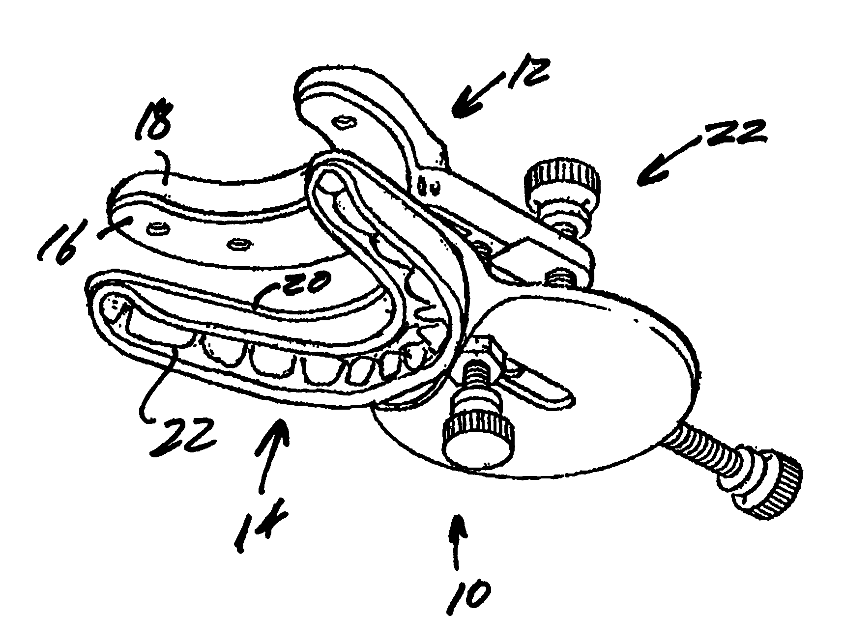
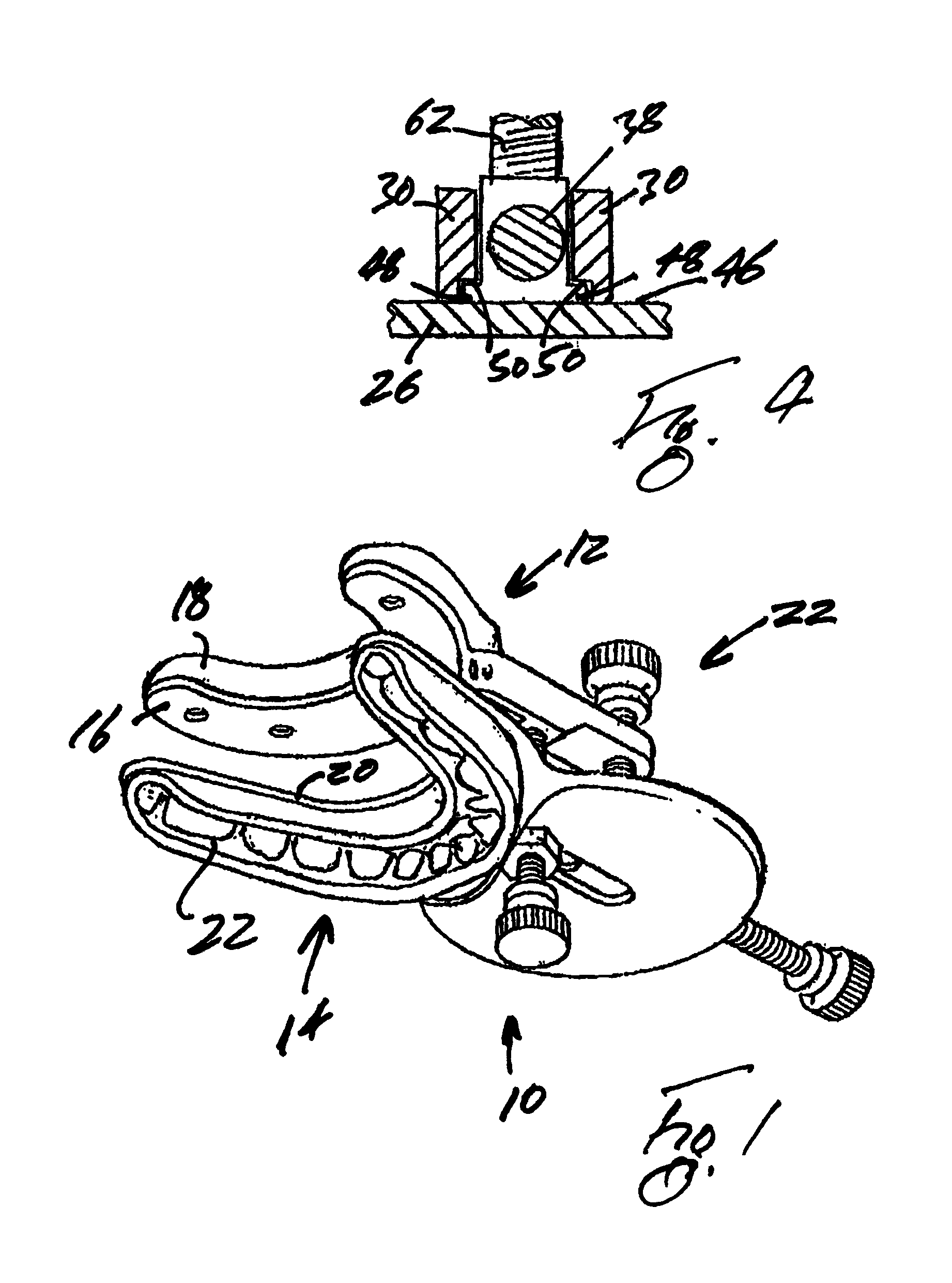
[0028]The mandible positioning device (also referred to herein as a pharyngeal airway adapter) shown in FIG. 1 is indicated generally by reference numeral 10 and comprises a maxillary dentition engagement component or upper bite block indicated generally by reference numeral 12 and a mandibular dentition engagement component or lower bite block indicated generally by reference numeral 14.

[0029]More particularly, the upper bite block 12 compr...


PUM


Abstract

A pharyngeal airway adjuster, or mandible positioning device, has a maxillary dentition engagement component and a mandibular dentition engagement component, each on opposite sides of a plane extending therebetween. An adjustable connection couples the maxillary dentition engagement component with the mandibular dentition engagement component. The adjustable connection has a first adjustment screw having a longitudinal axis parallel to the plane and a second adjustment screw having a longitudinal axis perpendicular to the plane. The first and second adjustable screws are independently adjustable and structured to effect horizontal and vertical displacement, respectively, of the maxillary dentition engagement component relative to the mandibular dentition engagement component. The pharyngeal airway adjuster has a number of indicators adapted to indicate the amount of forwardly and rearwardly displacement effected by the first adjustment screw and / or the amount of upwardly and downwardly displacement effected by the second adjustment screw.

Description

CROSS-REFERENCE TO RELATED APPLICATIONS[0001]This application is a continuation-in-part of U.S. patent application Ser. No. 10 / 635,483 filed 7 Aug. 2003, now U.S. Pat. No. 7,448,388, the contents of which are incorporated herein by reference.BACKGROUND OF THE INVENTION[0002]1. Field of the Invention[0003]The present invention relates to mandible positioning devices for use as pharyngeal airway adjusters.[0004]2. Description of the Related Art[0005]In patients who are suffering from the sleep disorder known as obstructive sleep apnea, the flesh and muscles of the tongue and throat relax, as the patients attempt to sleep, so that the pharyngeal airway is blocked and, consequently, the patients briefly stop breathing. When this occurs, the patients are awakened by the consequent lack of oxygen and blood, which often occurs with a loud snort or a bodily jerk.[0006]For the proper diagnosis and treatment of patients subject to sleep apnea, polysomnographic testing of the patients is perfo...

Claims


Application Information

Patent Timeline
Patent Type & Authority Patents(United States)
IPC IPC(8): A61F5/56
CPCA61F5/566
Inventor HALSTROM, LEONARD W.DIACOPOULOS, ELIAS G.
Owner PHILIPS RS NORTH AMERICA LLC
Why Eureka
Try Eureka