Stator vane having both chordwise and spanwise camber

a technology of chordwise and spanwise camber, which is applied in the direction of positive displacement liquid engine, piston pump, liquid fuel engine, etc., can solve the problems of source of objectionable noise or vibration, and not being able to achieve sympathetic vibration

Active Publication Date: 2010-11-16
VALEO INC
View PDF20 Cites 17 Cited by
  • Summary
  • Abstract
  • Description
  • Claims
  • Application Information

AI Technical Summary

Benefits of technology

[0005]An object of the invention is to provide an improved fan mounting system.

Problems solved by technology

However, in practice, this ideal is not attained, and the motor 12 and the inner ring 9 can move in an axial or tangential fashion, which is not desired.
In general, such sympathetic vibration is not desired.
A sympathetic vibration of the fan system can be the source of objectionable noise or vibration that can be noticed within the passenger compartment.

Method used


Image

  • Stator vane having both chordwise and spanwise camber
  • Stator vane having both chordwise and spanwise camber
  • Stator vane having both chordwise and spanwise camber

Examples


Embodiment Construction

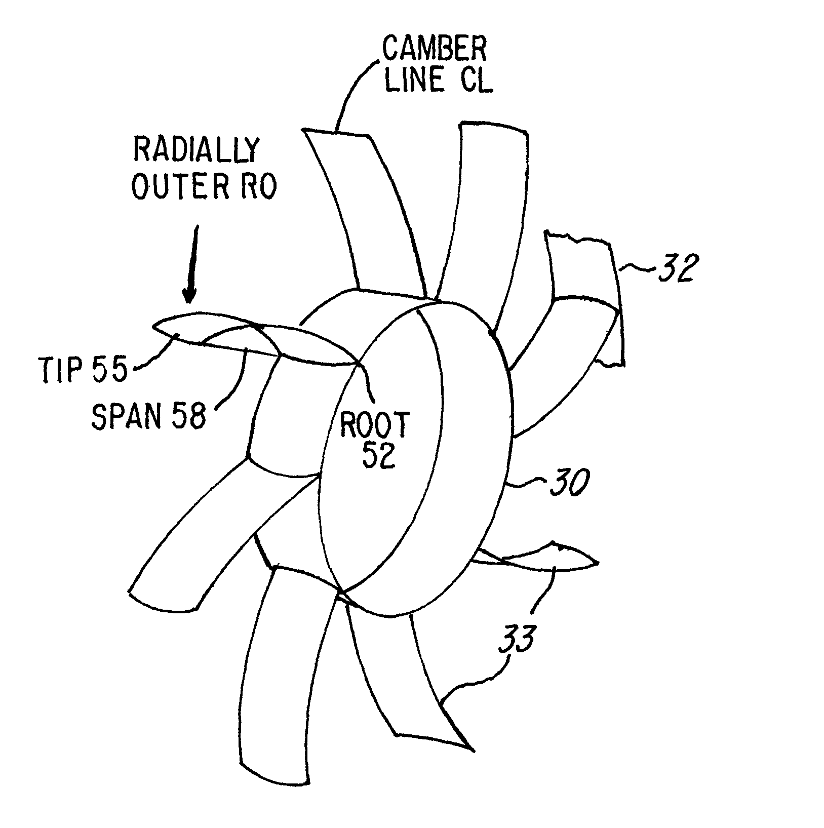
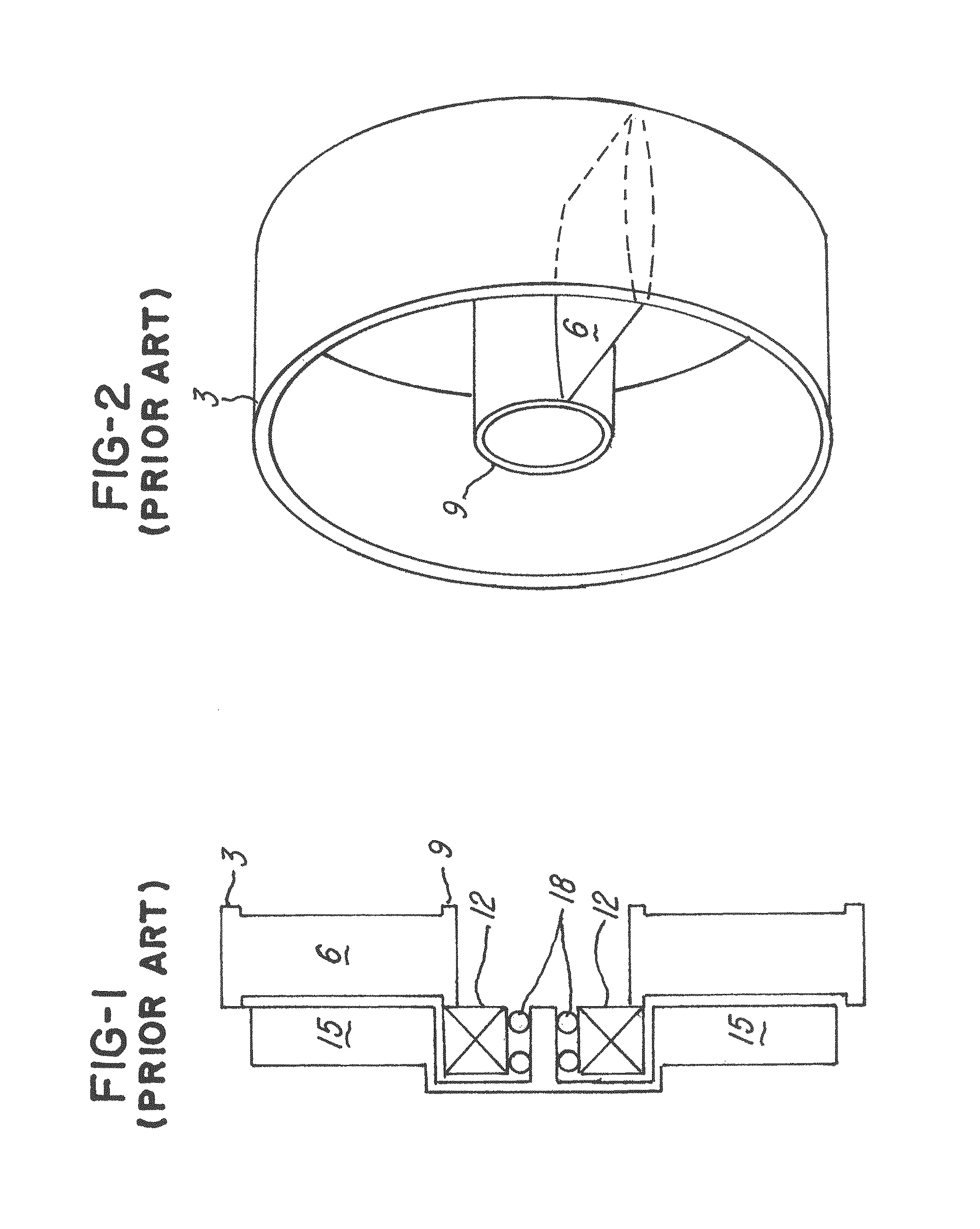
[0030]FIG. 3 is a simplified rendition of one form of the invention, showing a motor mount ring 30, which is analogous in function to inner mounting ring 9 in FIGS. 1 and 2. In FIG. 3, stator vanes 33 are attached to the inner ring 9, and also to an outer ring, or individual support members shown as element 32, which is analogous in function to outer ring 3 in FIGS. 1 and 2.

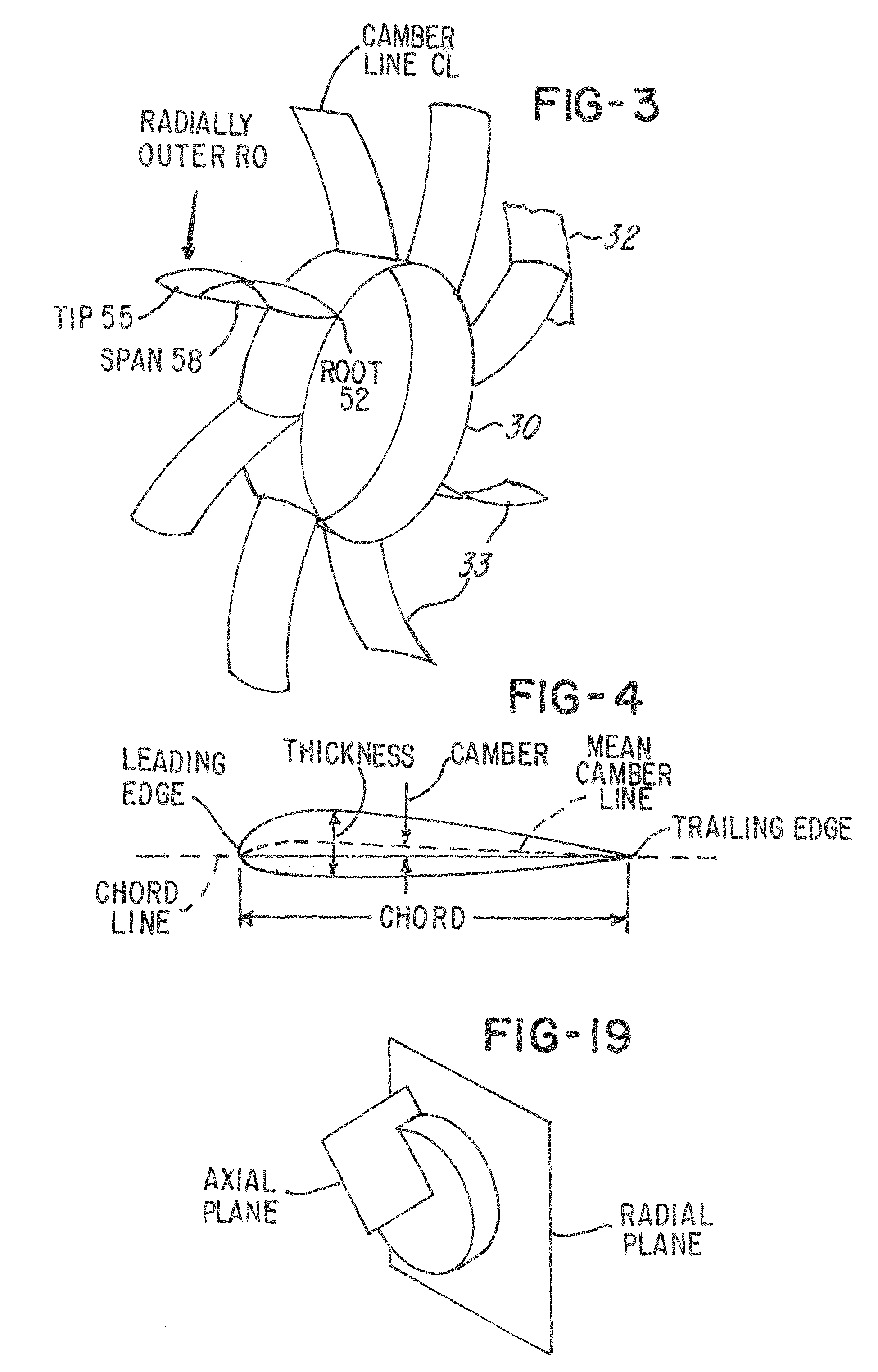
[0031]In FIG. 3, the stator vanes 33 are constructed with two types of camber. Camber generally is illustrated in FIG. 4, which illustrates a cross-sectional view of an airfoil. The mean camber line is the line which is midway between the lower and upper surfaces, with the distance being measured perpendicular to the mean camber line. The forwardmost point of the airfoil is the leading edge, and the rearmost point is the trailing edge, as indicated.

[0032]The straight line connecting the leading edge and the trailing edge is the chord line. The camber is the maximum distance between the mean camber line and the ch...


PUM


Abstract

A support system for a cooling fan for a heat exchanger. A suspension system supports an inner hub inside an outer support structure. The inner hub or ring supports the fan and motor. The suspension system includes an array of spiral support arms, extending from the inner hub to the outer supports. These arms have both spanwise and chordwise camber. The particular suspension system increases natural frequencies of the support system, over that wherein purely radial arms connect the inner hub and outer supports.

Description

[0001]The invention concerns stator vanes which support a cooling fan motor, such as in an automotive application. The stator vanes have cambered airfoil cross sections and also have camber along their lengths, or spans.BACKGROUND OF THE INVENTION[0002]FIG. 1 is a simplified cross-sectional schematic drawing of a cooling fan. Ring 3, also shown in FIG. 2, supports an array of radial stator vanes 6, shown in both Figures. Ring 3 is anchored to an external support (not shown). Stator vanes 6 in FIG. 1 support an inner ring 9, which is also shown in FIG. 2. It should be understood that the structure identified as ring 9 does not have to take the form of a ring or a complete cylindrical 360° body of revolution. Inner ring 9 in FIG. 1 supports a motor, diagrammatically indicated as motor 12, which may be an electric or hydraulic motor. Motor 12 drives fan blades 15, which are supported by bearings 18.[0003]Ideally, inner ring 9 acts as a perfectly rigid support for the motor 12. However,...

Claims


Application Information

Patent Timeline
Patent Type & Authority Patents(United States)
IPC IPC(8): F04D29/54
CPCF04D29/542F04D29/666F04D29/544
Inventor HASAN, ATIFSAVAGE, JOHN R.
Owner VALEO INC
Why Eureka
Try Eureka