Frayless frangible connection for fabric and vertical blind system incorporating the same

a vertical blind system and fabric technology, applied in the field of frangible connection, can solve the problems of affecting the comfort of the occupants, requiring extra steps to cut the fabric accurately, and affecting the strength or appearance of the fabric in the finished product,

Inactive Publication Date: 2010-11-23
LACE LASTICS
View PDF10 Cites 16 Cited by
  • Summary
  • Abstract
  • Description
  • Claims
  • Application Information

AI Technical Summary

Problems solved by technology

The cutting of fabric, however, introduces a number of problems which may present themselves during manufacture, most notably that extra steps are required to cut the fabric accurately.
Likewise, by its very nature, cutting interrupts the fabric matrix, leaving a frayed edge which can undermine the strength or appearance of the fabric in the finished product.
For instance on sunny days in warm climates, the sun is too strong (and too hot) for the comfort of the occupants, as well as being damaging to interior furnishings that may fade or become brittle.
In large windows or doors, venetian blinds are impractical because they can become difficult to raise completely when needed for unobstructed viewing, or to clean the glass behind.
These louvers are generally limited to solid colors, or simple vertical patterns, because they are manufactured separately.
If a continuous horizontal pattern effect is attempted using this method, it is prohibitively difficult accurately to align sequential louvers horizontally.
Each louver in a horizontal pattern represents an individual pattern segment even slight misalignment of which would be unattractively obvious and would destroy the aesthetic appeal of the blind.
This production method makes the incorporation of a horizontal pattern prohibitively difficult because there is no way to assure that pattern elements will align horizontally.
Even if the louvers were cut transversely from rolls of patterned fabric having a width equal to the length of the louver, further processing such as the attachment of mounting hardware to each of the louvers would introduce sufficient vertical error into each louver to destroy the horizontal alignment of the pattern.
Fabric louvers manufactured from a single roll of fabric have an additional drawback in the tendency of the louvers to fray along their longitudinal edges, particularly as a result of machine washing.
Because the material from which the louvers are cut necessarily has an existing continuous structure, the cutting of which necessarily presents edges where the structure has been interrupted, resulting in a series of loose threads.
Untreated, these threads tend to unravel, weakening the fabric and creating an unattractive frayed edge over time and as laundered.
Preventing this result requires additional costly manufacturing steps.
Such a blind can be expensive to manufacture, as the sheer fabric must be attached to the vanes during an additional manufacturing step because the vanes are made of a different material from the fabric.
Furthermore, although the width of a conventional vertical blind can be adjusted by adding or removing a number of discreet vanes, this is not possible in a combination blind because the vanes are essentially connected together into a single structure by the sheer fabric, requiring these blinds to be custom made to a specific width, also adding to their expense.
One obvious drawback, in addition to the drawbacks discussed with respect to Colson et al. above, is that the rigid vanes overlap the fabric requiring excessive fabric in order to fabricate the entire window covering.
Further, the vanes or louvers are only attached to the fabric material along a top and bottom edge thereof, thereby inhibiting the control over the fabric material during operation of the window covering.
Although this embodiment overcomes some of the limitations of the first Shapiro embodiment, a disadvantage of such a blind would be due to the lack of stiffness of the fine mesh “louver” sections.
Any attempt to rotate the louvers of the second Shapiro embodiment would be resisted progressively along the length of the louver, resulting in an unattractive, non-uniform twisting which would render the blind nonfunctional.

Method used


Image

  • Frayless frangible connection for fabric and vertical blind system incorporating the same
  • Frayless frangible connection for fabric and vertical blind system incorporating the same
  • Frayless frangible connection for fabric and vertical blind system incorporating the same

Examples


Embodiment Construction

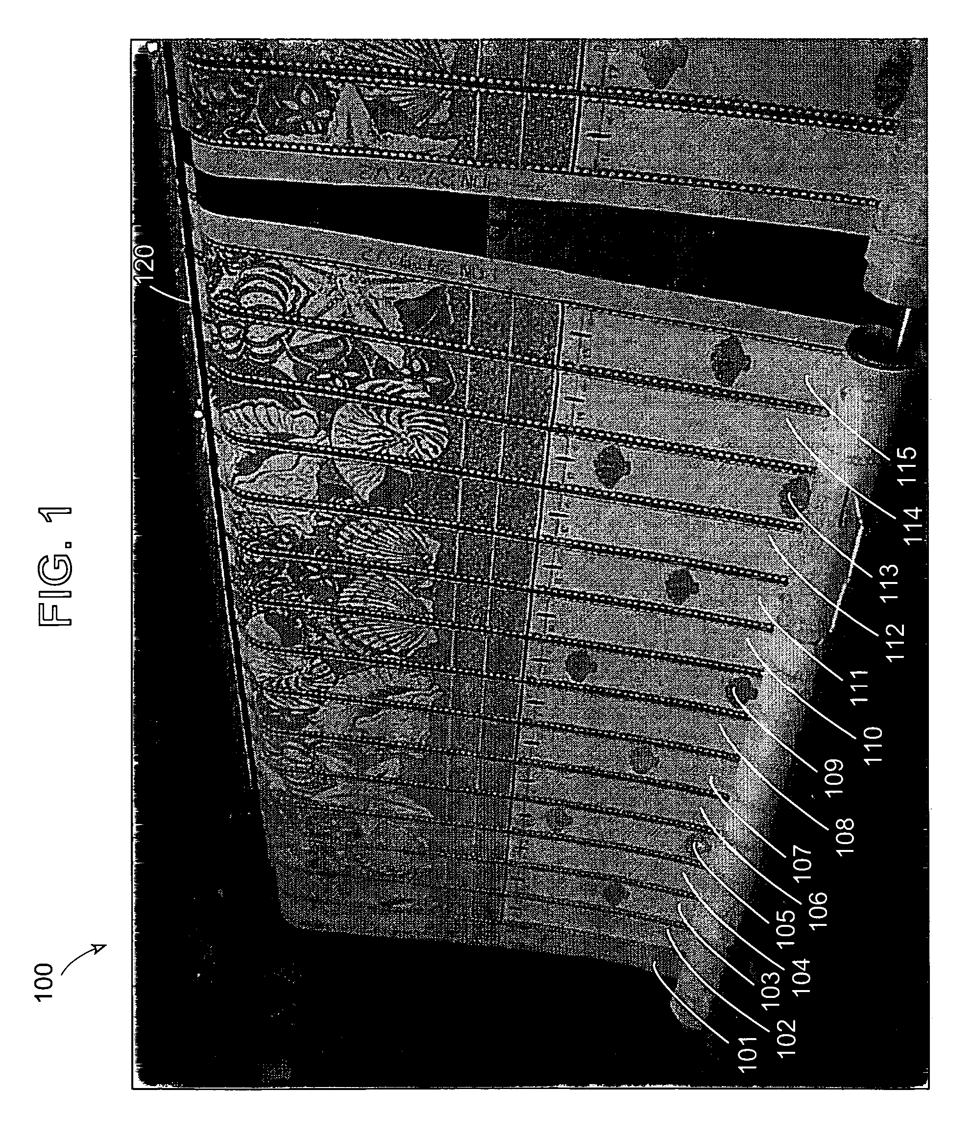
[0060]An arrangement of a first embodiment of a vertical blind incorporating the present invention is shown in FIG. 1. FIG. 1 illustrates a single fabric panel 100 comprising fifteen louvers of a vertical blind 101-115. This window treatment has a pattern 120 that spans the width of the panel. As illustrated, the design continues from one louver to the next. The individual louvers for this window treatment have been knit in a single panel to be separated after they are finished, as described below, assuring an accurate alignment of the pattern when installed. Each of louvers 101-115 are separated by a tear away fringe, which enables the louvers to be separated for installation.

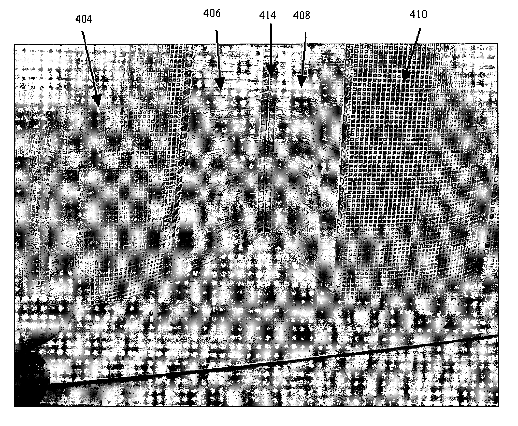
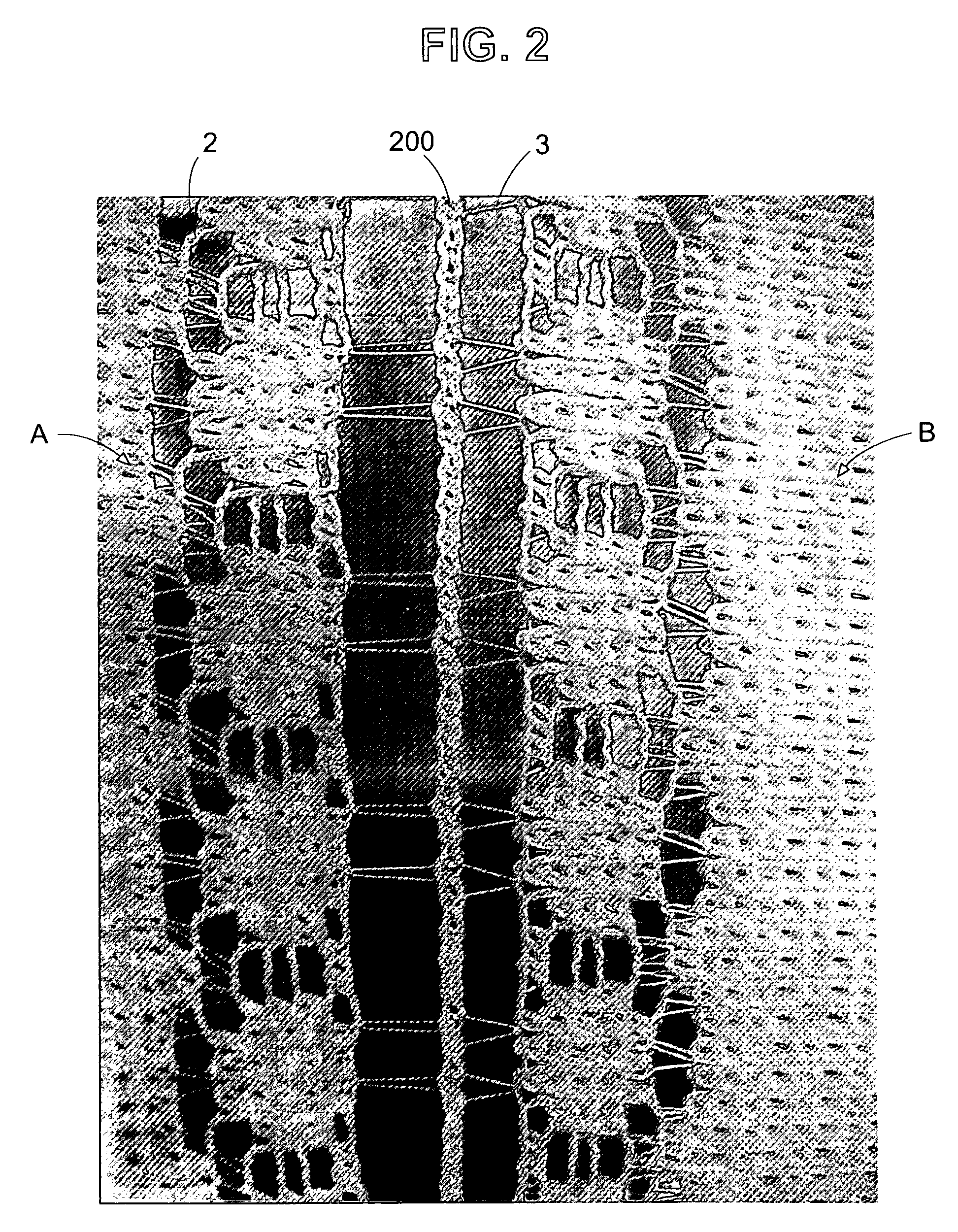
[0061]FIG. 2 is a detail of the tear away fringe 200 of the present invention. The tear away fringe 200 is shown running vertically between two adjacent louvers A and B. Connector yarns 2 and 3 are shown connecting tear away fringe 200 to the edge of louvers A and B respectively. Prior to installation of the l...


PUM


Abstract

A vertical blind panel including a plurality of substantially opaque louvers and a plurality of sheer transparent or translucent spacers. Each of the plurality of spacers is disposed between a respective pair of the plurality of louvers. At least one of the plurality of louvers includes a first vertically oriented louver portion connected to a second vertically oriented louver portion.

Description

RELATED APPLICATIONS[0001]This application is a continuation-in-part of U.S. patent application Ser. No. 10 / 960,533, filed Oct. 7, 2004, now U.S. Pat. No. 7,730,927 the contents of which are incorporated herein by reference in their entirety, and which claims priority to U.S. Provisional Patent Application Ser. No. 60 / 562,333, filed Apr. 14, 2004.FIELD OF THE INVENTION[0002]The present invention relates to a frangible connection knitted into a fabric panel during manufacture. More specifically, the present invention relates to a vertical blind system having decorative louvers which are knitted in a single panel and attached together by a knitted frangible hinge or tear away fringe.BACKGROUND OF THE INVENTION[0003]When knitting a large fabric panel, it is often the case that the finished fabric will be cut into smaller pieces for use in a finished product, such as a window treatment. The cutting of fabric, however, introduces a number of problems which may present themselves during m...

Claims


Application Information

Patent Timeline
Patent Type & Authority Patents(United States)
IPC IPC(8): E06B3/48D04B21/08E06B3/12E06B3/32E06B9/30E06B9/36E06B9/386
CPCD04B19/00D04B21/08D04B21/20E06B9/36E06B9/386D10B2503/03
Inventor GRAICHEN, CLAUS
Owner LACE LASTICS
Why Eureka
Try Eureka