Microphone mounting system for acoustic stringed instruments

a technology for acoustic instruments and mounting systems, which is applied in the direction of mouthpiece/microphone attachments, piezoelectric/electrostrictive transducers, instruments, etc., can solve the problems of affecting the sound quality of the instrument, so as to achieve the effect of convenient use and effective clamping mechanism

Inactive Publication Date: 2010-11-30
BANKS BILLY STEVEN
View PDF22 Cites 21 Cited by
  • Summary
  • Abstract
  • Description
  • Claims
  • Application Information

AI Technical Summary

Problems solved by technology

These attempts have all suffered from significant disadvantages, typically through compromising the quality of the sound produced by the instrument, or the structure of the instrument, or both.
Current solutions for acoustic amplification typically cause acoustic instruments to sound artificial and distorted.
Previous attempts to amplify acoustic stringed instruments have included the installation of electric pickup and piezoelectric amplification systems that alter the instrument's tone and render the instrument unplayable without amplification, i.e. render the instrument no longer suitable for unamplified acoustic sound production.
Additionally, these methods and associated devices are often expensive, often permanently alter or damage the instrument, and achieve less than desirable resulting sound quality.
Attempts to provide amplification by simply attaching microphones to the body of the instrument have also proven bulky and ineffective for use with hand-held instruments, particularly violins, that may involve significant body movement when playing.
Devices that mount a microphone inside an acoustic instrument typically provide poor feedback control and offer limited adjustability to the instrument player.
In addition, such devices typically require some incursion and damage to the structure of the instrument to effect installation.
Prior art devices also typically do not provide sufficient cable support and stability.

Method used


Image

  • Microphone mounting system for acoustic stringed instruments
  • Microphone mounting system for acoustic stringed instruments
  • Microphone mounting system for acoustic stringed instruments

Examples


Embodiment Construction

[0028]As required, a detailed embodiment of the present invention is disclosed herein; however, it is to be understood that the disclosed embodiment is merely exemplary of the invention, which may be embodied in various forms. Therefore, specific structural and functional details disclosed herein are not to be interpreted as limiting, but merely as a basis for the claims and as a representative basis for teaching one skilled in the art to variously employ the present invention in virtually any appropriately detailed structure.

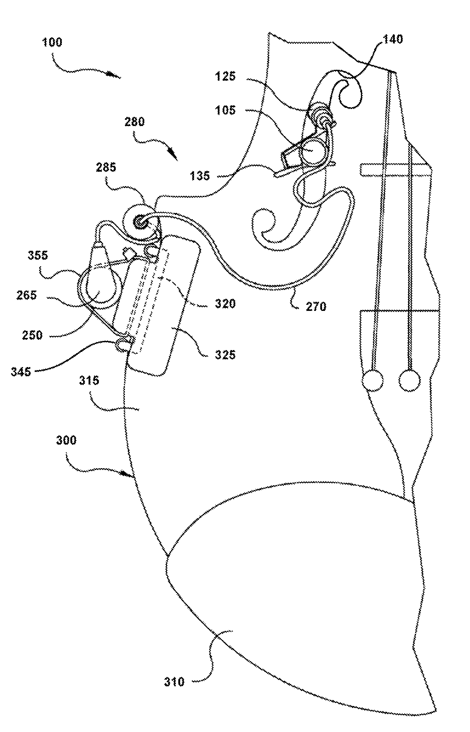
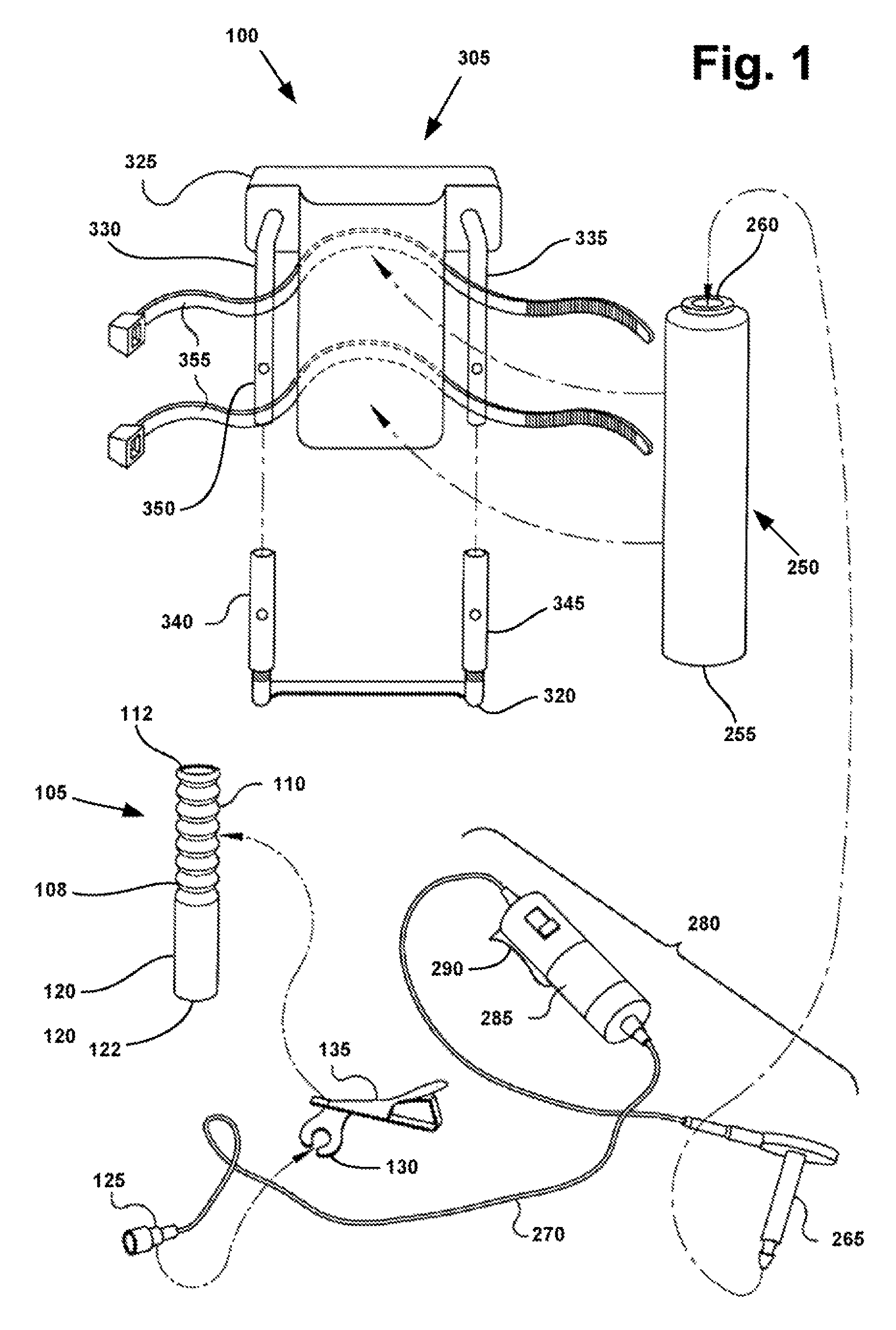
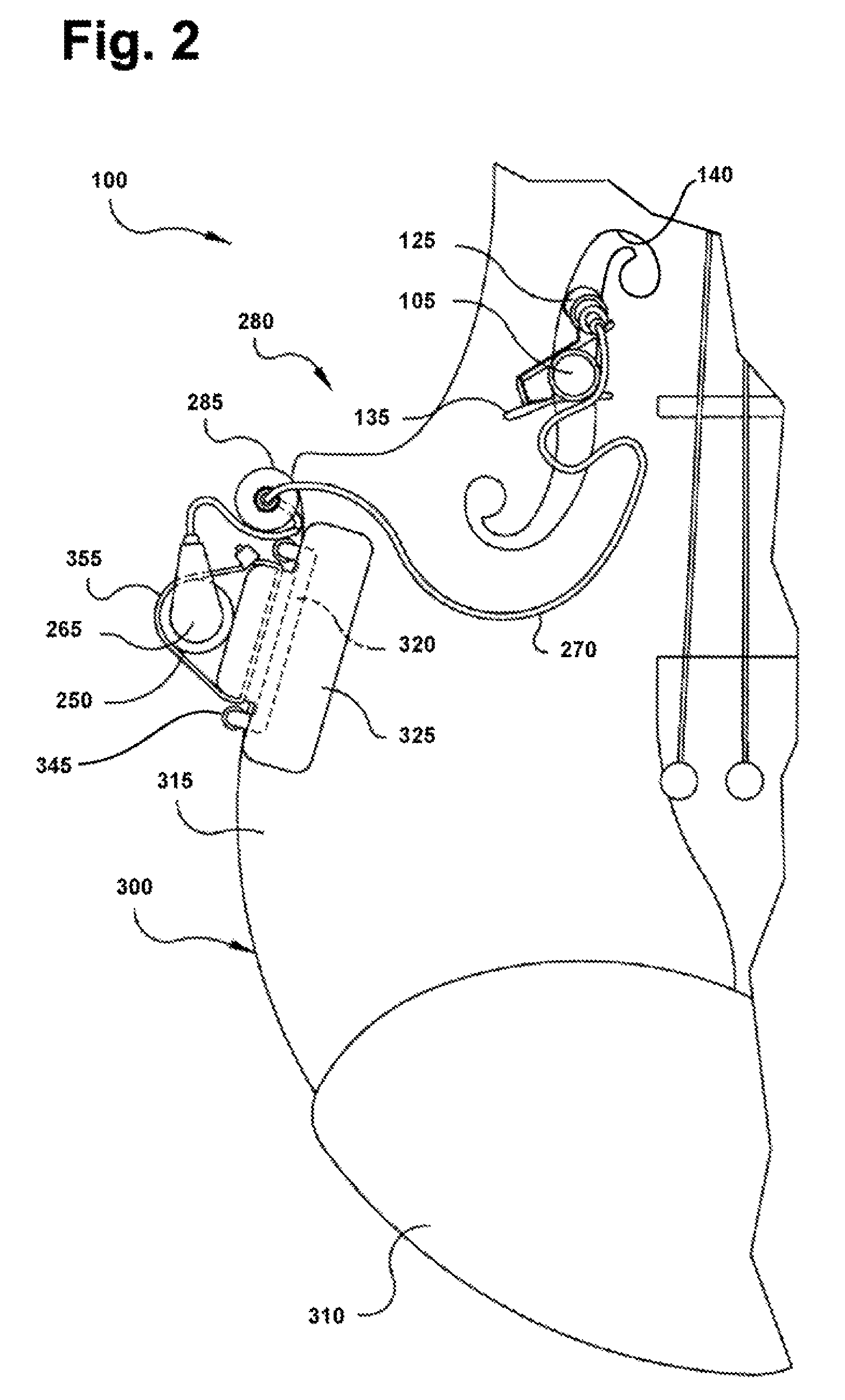
[0029]Referring now to FIGS. 1 through 5 of the drawings, there are shown embodiments of a microphone mounting system indicated by the reference numeral 100. The main microphone mounting component is a post or grip 105 elongated along its longitudinal axis. The grip 105 is resilient and may comprise a hollow, corrugated plastic tube as shown in FIGS. 1, 3 and 4.

[0030]The grip 105 has an upper portion 110 extending from approximately the midpoint 108 to the uppe...


PUM


Abstract

A microphone mounting system for an acoustic, stringed instrument that places the microphone in sufficient proximity to the instrument sound hole to capture the warmth and tone of the instrument while assisting in feedback control, and without altering or damaging the finish or structure of the instrument. The system includes a grip, such as a corrugated plastic tube, attached to a microphone and wedged into the instrument sound bole to be held in place through frictional engagement. The microphone is connected to an instrument cable coupler, clamped to the side of the instrument, which is then connected to a sound amplification system.

Description

CROSS REFERENCE TO RELATED APPLICATION[0001]This application claims priority from provisional patent application No. 60 / 911,255 filed on Apr. 11, 2007.BACKGROUND OF THE INVENTION[0002]1. Field of the Invention[0003]This invention relates to devices for mounting microphones in proximity to acoustic instruments, and, more particularly, to a system for temporarily mounting a microphone in close proximity to the sound hole of an acoustic instrument by providing an attachment element that engages the sides of sound hole and avoids alteration and / or damage to the body of the instrument.[0004]2. Description of the Related Art[0005]There have been numerous attempts to electrically amplify acoustic violins and other acoustic instruments with an F-style sound hole. These attempts have all suffered from significant disadvantages, typically through compromising the quality of the sound produced by the instrument, or the structure of the instrument, or both. Current solutions for acoustic amplif...

Claims


Application Information

Patent Timeline
Patent Type & Authority Patents(United States)
IPC IPC(8): H04R9/08H04R11/04H04R21/02H04R19/04H04R17/02G10D3/00
CPCH04R1/08
Inventor BANKS, BILLY STEVEN
Owner BANKS BILLY STEVEN
Why Eureka
Try Eureka