Blade server system and method of managing same

a blade server and server technology, applied in the direction of instrumentation, electrical apparatus construction details, support structure mounting, etc., can solve the problems of complex system configuration management and inability to take configurational information easily, and achieve the effect of easy management of configurational information and setting

Inactive Publication Date: 2010-11-30
NEC CORP
View PDF21 Cites 18 Cited by
  • Summary
  • Abstract
  • Description
  • Claims
  • Application Information

AI Technical Summary

Benefits of technology

[0007]It is an object of the present invention to provide a blade server system and a method of managing such a blade server system, which allow configurational information to be managed and set with ease.
[0011]According to the present invention, as described above, inasmuch as the configurations of the blade server and the chassis management module that are inserted in the slots of the back plane are uniformly managed by the blade server system in its entirety, the system management is made easier to perform than if performed by the conventional managing process using the SNMP. Furthermore, as the configurational information is acquired from the back plane, configurations can easily be reset in the event of a failure of the blade server and the chassis management module. As described above, the present invention offers advantages in that the blade server system can uniformly be managed easily and allows configurational changes to be made easily.

Problems solved by technology

According to the conventional system management using the SNMP, however, since the configurational information of the devices is managed individually by the respective devices, but not uniformly by the system in its entirety, the management of the system configurations is complex.
In addition, if a device needs to be replaced due to the occurrence of a fault, then as the faulty device carries its configurational information, the configurational information cannot easily be taken over.

Method used


Image

  • Blade server system and method of managing same
  • Blade server system and method of managing same
  • Blade server system and method of managing same

Examples


Embodiment Construction

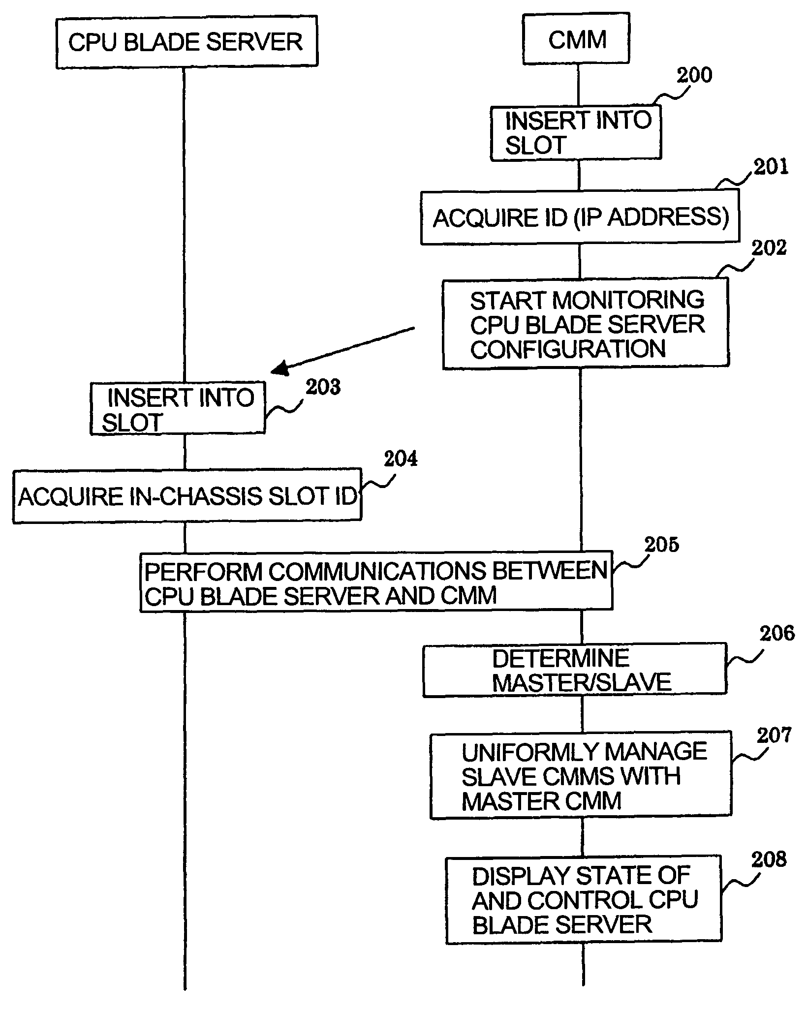
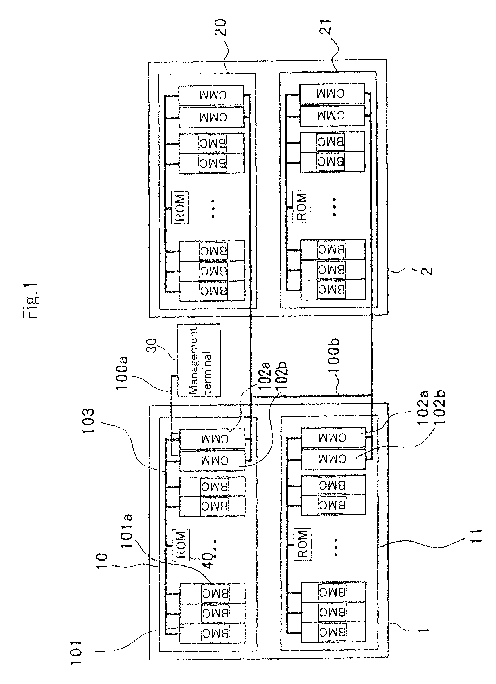
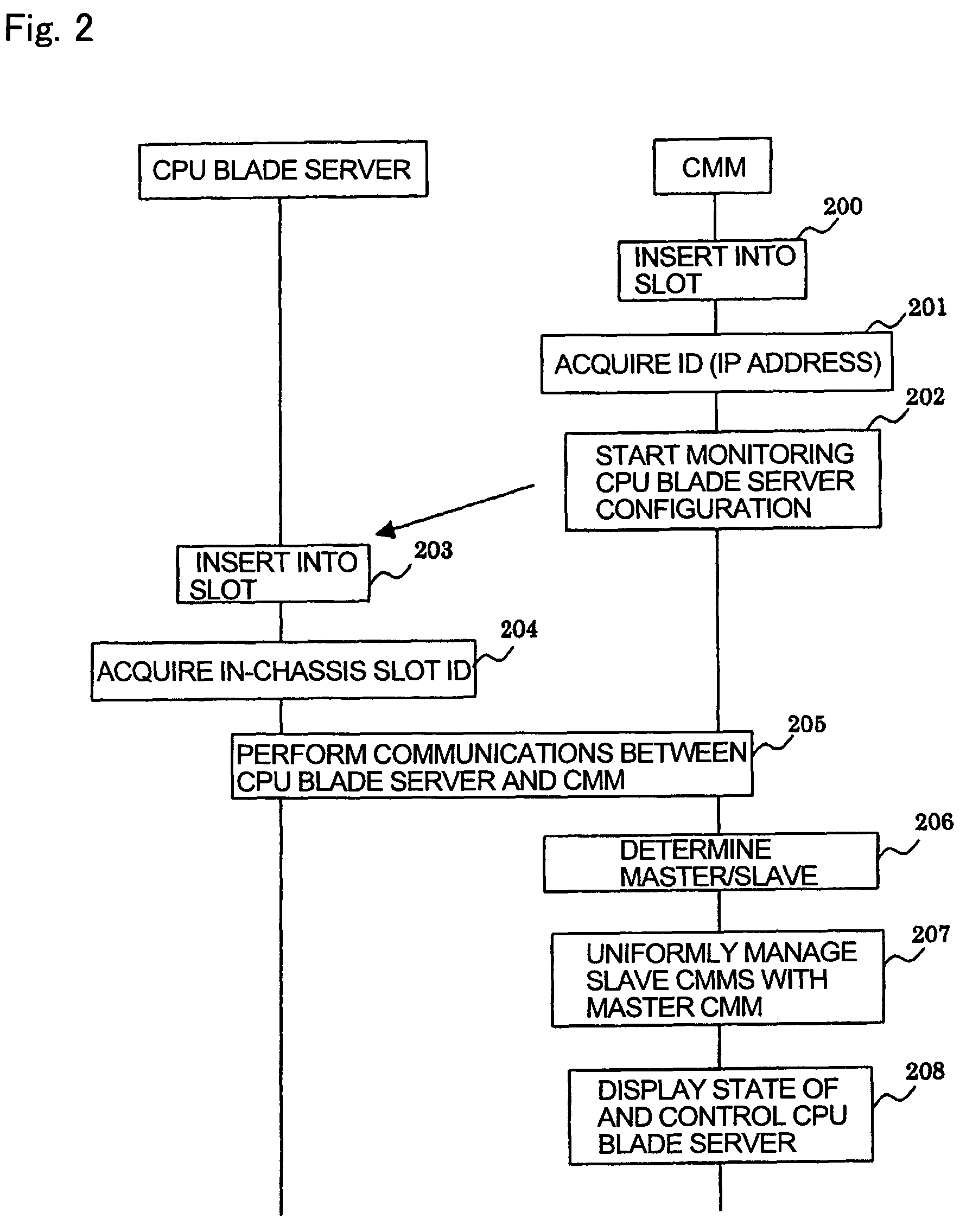
[0016]FIG. 1 shows in block form a general arrangement of a blade server system according to an embodiment of the present invention. As shown in FIG. 1, the blade server system has housing 1 accommodating chassis 10, 11 therein and housing 2 accommodating chassis 20, 21.

[0017]Chassis 10 has back plane 103 in the form of a circuit board or a device with a plurality of slots. A plurality of CPU blade servers 101 and two CMMs (Chassis Management Modules) 102a, 102b are inserted respectively in the slots of back plane 103. Chassis 10 also accommodates therein a power supply unit and a cooling fan. Electric power and input / output (I / O) interface signals are supplied to CPU blade servers 101 and CMMs 102a, 102b through back plane 103. CMMs 102a, 102b are of a redundant structure in which one of CMMs 102a, 102b serves as a primary CMM and the other a secondary CMM. If the primary CMM fails, then the secondary CMM takes over operation.

[0018]Each of CPU blade servers 101 has components requi...


PUM


Abstract

Each chassis includes a back plane having a plurality of slots and a CPU blade server and CMMs which are inserted in the slots, respectively. The back plane has a storage unit storing a housing number for identifying the housing, in-housing chassis numbers for identifying the chassis in the housing, and in-chassis slot IDs for identifying the slots. When the blade server is inserted into the corresponding slot, the blade server acquires the in-chassis slot ID from the back plane. When the CMMs are inserted into the corresponding slots, the CMMs acquire housing numbers and in-housing chassis numbers from the back plane, holds the housing number and the in-housing chassis numbers, and manages the configuration of the blade server through the back plane. One of the CMMs manages the other CMMs.

Description

BACKGROUND OF THE INVENTION[0001](1) Field of the Invention[0002]The present invention relates to the system management of a blade server.[0003](2) Description of the Related Art[0004]There is known a blade server system having a plurality of blades each including components required to provide a server, e.g., a CPU, a hard disk, etc. mounted on a single board, the blades being housed in a chassis (blade housing unit). The chassis also accommodates therein a power supply unit and a cooling fan that are required to operate the housed blades, and a network switch for making it possible to perform data communications between the blades. Usually, the chassis housing the blades is placed in a housing.[0005]For performing the system management of the blade server system, there has been known a process using SNMP (Simple Network Management Protocol) as disclosed in Japanese laid-open patent publication No. 2004-213651. According to the system management using the SNMP, the network between ...

Claims


Application Information

Patent Timeline
Patent Type & Authority Patents(United States)
IPC IPC(8): H05K7/10G06F13/00G06F15/177G06F15/00
CPCH05K7/1459H05K7/1498
Inventor TANAKA, YOSHIMASA
Owner NEC CORP
Why Eureka
Try Eureka