Printer having differential filtering smear correction

Inactive Publication Date: 2010-12-07
EASTMAN KODAK CO
View PDF37 Cites 3 Cited by
  • Summary
  • Abstract
  • Description
  • Claims
  • Application Information

AI Technical Summary

Benefits of technology

[0011]It is an advantageous effect of the invention that an improved printers and methods having digital filtering that reduces smear.
that an improved printers and methods having digital filtering that reduces smear.

Problems solved by technology

In offset printing applications, master cylinders or plates wear over time.
That wear, in conjunction with high speed printing causes smear down the printed page comparable to thermal smear.
This tends to increase smear.
Unfortunately, the more an image is sharpened, the more any noise and artifacts in the image are also amplified.
These techniques can modify middle and high frequency content, but are not particularly effective in reducing smear.
For example, sharpening algorithms are generally either circular or elliptically symmetric and sharpen uniformly across and down the page, and do not distinguish between rising and falling edges.

Method used


Image

  • Printer having differential filtering smear correction
  • Printer having differential filtering smear correction
  • Printer having differential filtering smear correction

Examples


Embodiment Construction

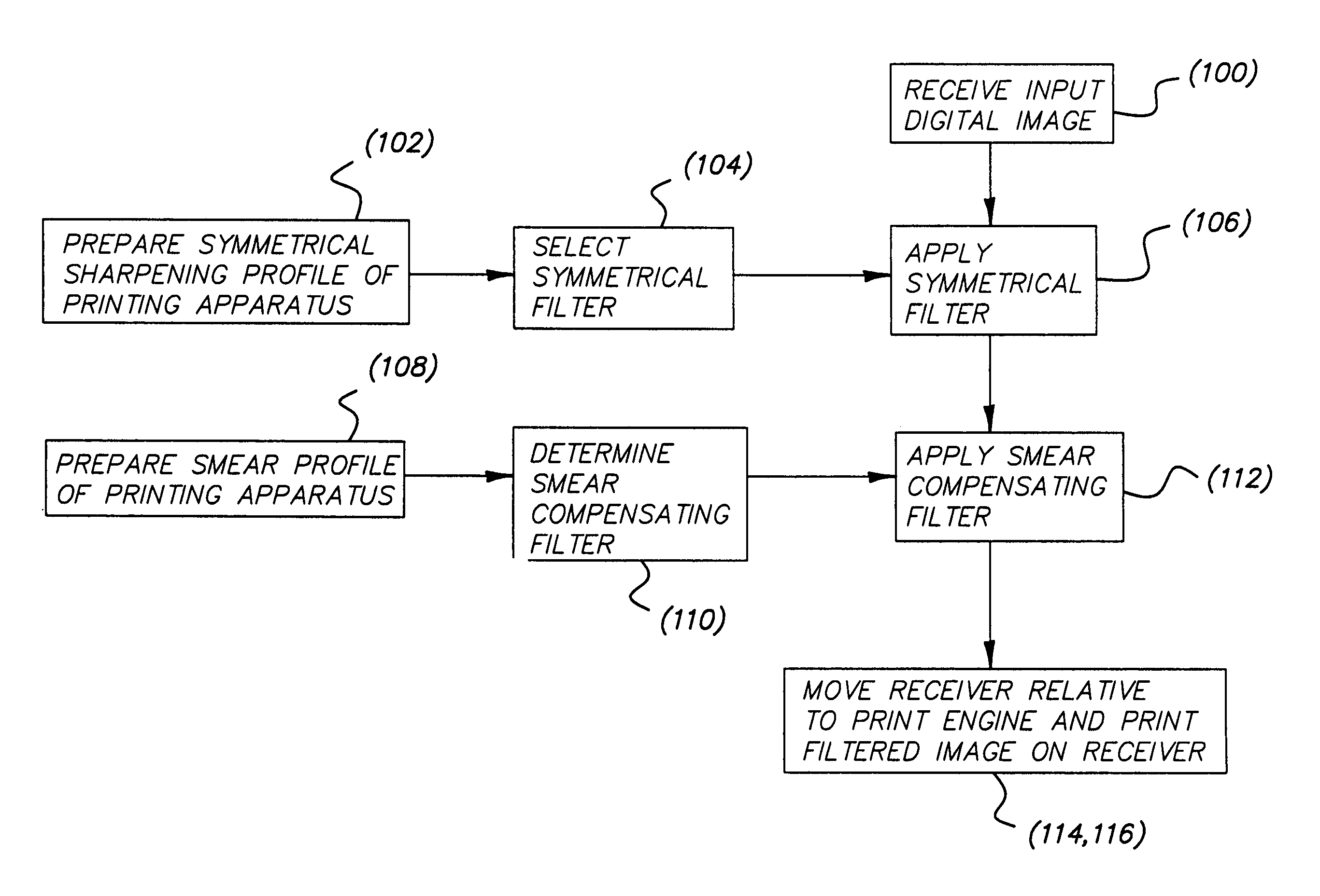
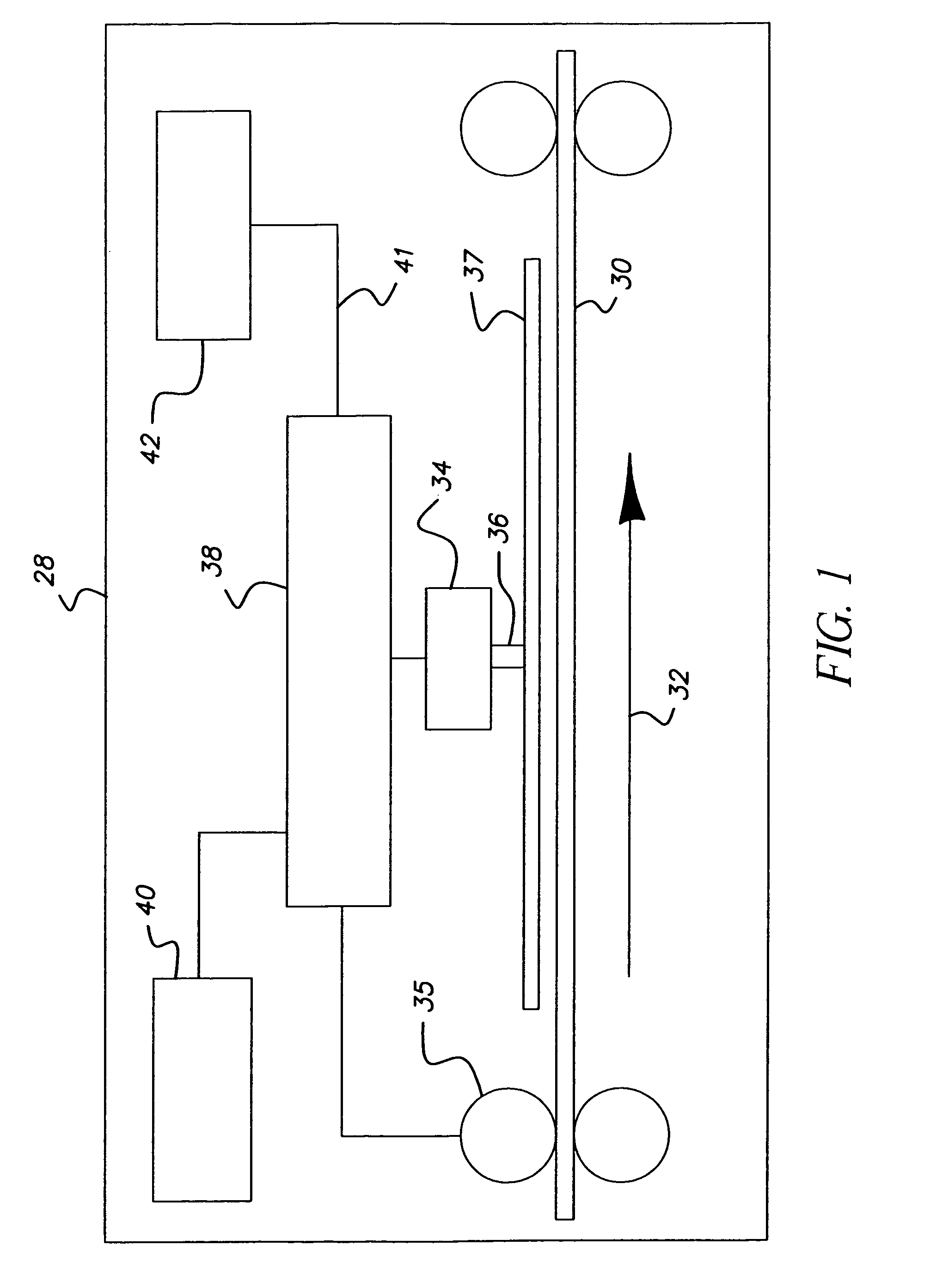
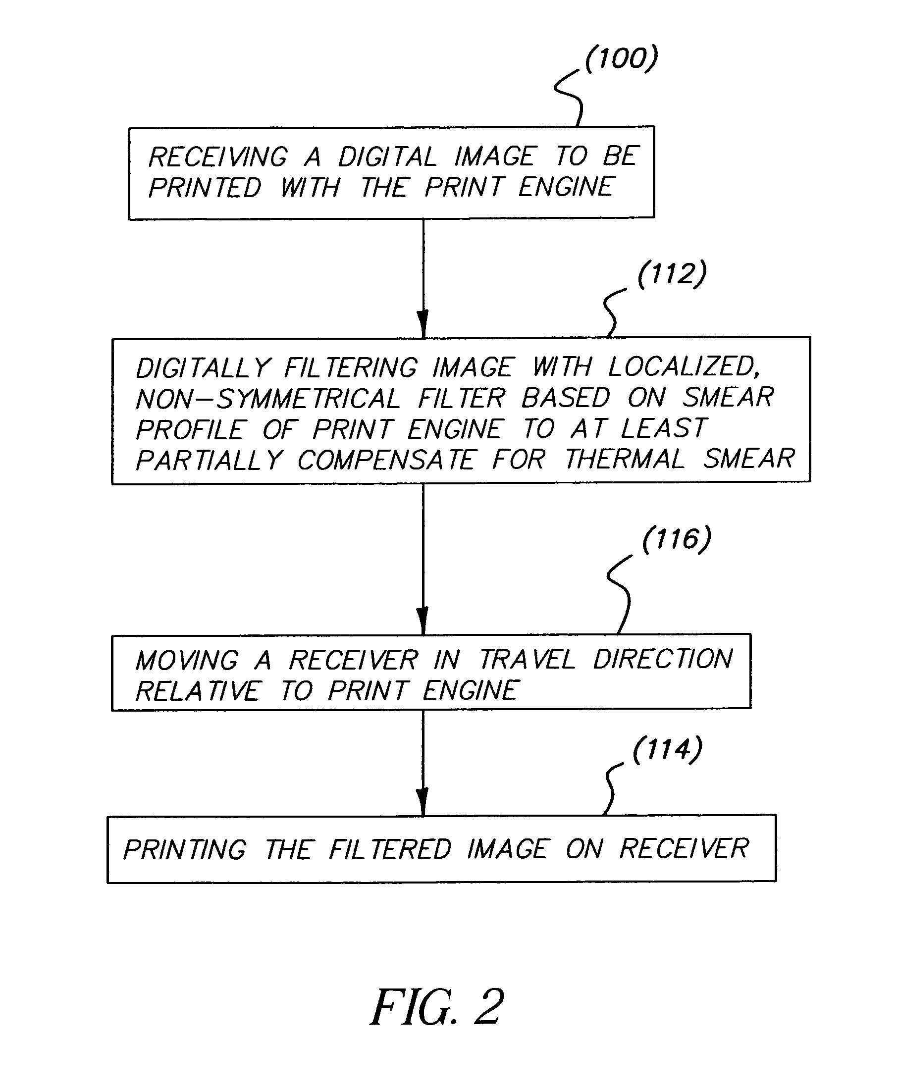
[0027]In the methods and apparatus herein, smear is reduced by digital filtering that is localized and non-symmetrical. The term “smear” is used herein to refer to erroneous increases or decreases in density or equivalent image unit values of a visible image. Smear can be due to a physical transfer of an image component, such as transfer of ink or the like from an intended image unit of an image to a neighboring image unit as a result of contact during relative movement of an image carrier and an image generator. For example, an offset printing press transfers ink from a plate to a blanket to a receiver. The transfer of a spot of ink may be blurred in the motion direction of the plate to the blanket and of the blanket to the receiver. The blurring of the lead edge of the ink spot on the receiver may be different than the blurring of the trail edge. The method can compensate the image written onto the plate by a platesetter to correct for the smear.

[0028]Smear can also be due to an a...


PUM


Abstract

In a method and printing apparatus, a receiver is moved in a travel direction relative to a print engine. The print engine has a predetermined profile of smear in the travel direction at a plurality of sites on the receiver. Each site corresponds to a respective one of the pixels. A digital image to be printed with the print engine is received and digitally filtered based on the profile to provide a filtered image. The filtering is localized, non-symmetrical, and at least partially compensatory of the smear. As the receiver is moved, the filtered image is printed on the receiver, the printing being modulated in accordance with the filtered image.

Description

FIELD OF THE INVENTION[0001]This invention relates to printing and digital image processing methods and equipment and in particular to a printer and method providing differential filtering of images for smear correction.BACKGROUND OF THE INVENTION[0002]Thermal printers are often used to print photographic quality images for both in-store and in-home applications. Thermal dye printers transfer dye onto a page by heating dye on a donor material and having it migrate onto a receiver material. Resistive print heads are one of the most common methods of heating the dye on the donor. Resistive print heads utilize a stripe of tiny resistors, which are heated by selectively sending current through each. The stripe of resistors image an entire row of the image at a time. By varying the power through the resistor, the amount of dye is modulated to transfer from no dye transfer (Dmin) to maximum transfer (Dmax) in a continuous fashion. Because of this, thermal printers are continuous tone prin...

Claims


Application Information

Patent Timeline
IPC IPC(8): H04N1/407
CPCH04N1/4092G06T5/003H04N1/12H04N1/193G06T5/73
Inventor PTUCHA, RAYMOND W.SANGER, KURT M.
Owner EASTMAN KODAK CO
Why Eureka
Try Eureka