Thin-film design for positive and/or negative C-plate

a technology of c-plates and thin films, applied in the field of thin films, can solve the problems of large cost of growing and polishing large crystal plates, birefringent elements typically not generally suitable for compensation applications, and the c-plate does not provide any net retardation for normal-incident rays

Active Publication Date: 2010-12-07
VIAVI SOLUTIONS INC
View PDF38 Cites 11 Cited by
  • Summary
  • Abstract
  • Description
  • Claims
  • Application Information

AI Technical Summary

Problems solved by technology

Notably, a C-plate does not provide any net retardation for normal-incident rays (i.e., normal incident light is unaffected by the birefringence).
For example, while birefringent crystals are highly durable and / or stable compared to their organic and / or polymeric counterparts, the cost of growing and polishing large crystal plates can be significant.
In addition, since it is difficult to fabricate a birefringent crystal with a physical thickness less than about 100 microns, these naturally birefringent elements typically are not generally suitable for compensation applications.
Unfortunately, due to the layer thickness restrictions, the FBAR can only act as a negative C-plate.

Method used


Image

  • Thin-film design for positive and/or negative C-plate
  • Thin-film design for positive and/or negative C-plate
  • Thin-film design for positive and/or negative C-plate

Examples


Embodiment Construction

[0036]As discussed above, thin films are often used in anti-reflection coatings and / or in interference filters (e.g., thin film interference filters). In each case, the thin film coatings typically include at least one layer having a refractive index n and a physical thickness d selected such that the optical thickness (n times d) of the layer is equal to one quarter of the wavelength of the incident radiation. These quarter wave (QW) layers use the principles of interference to obtain the desired optical effects.

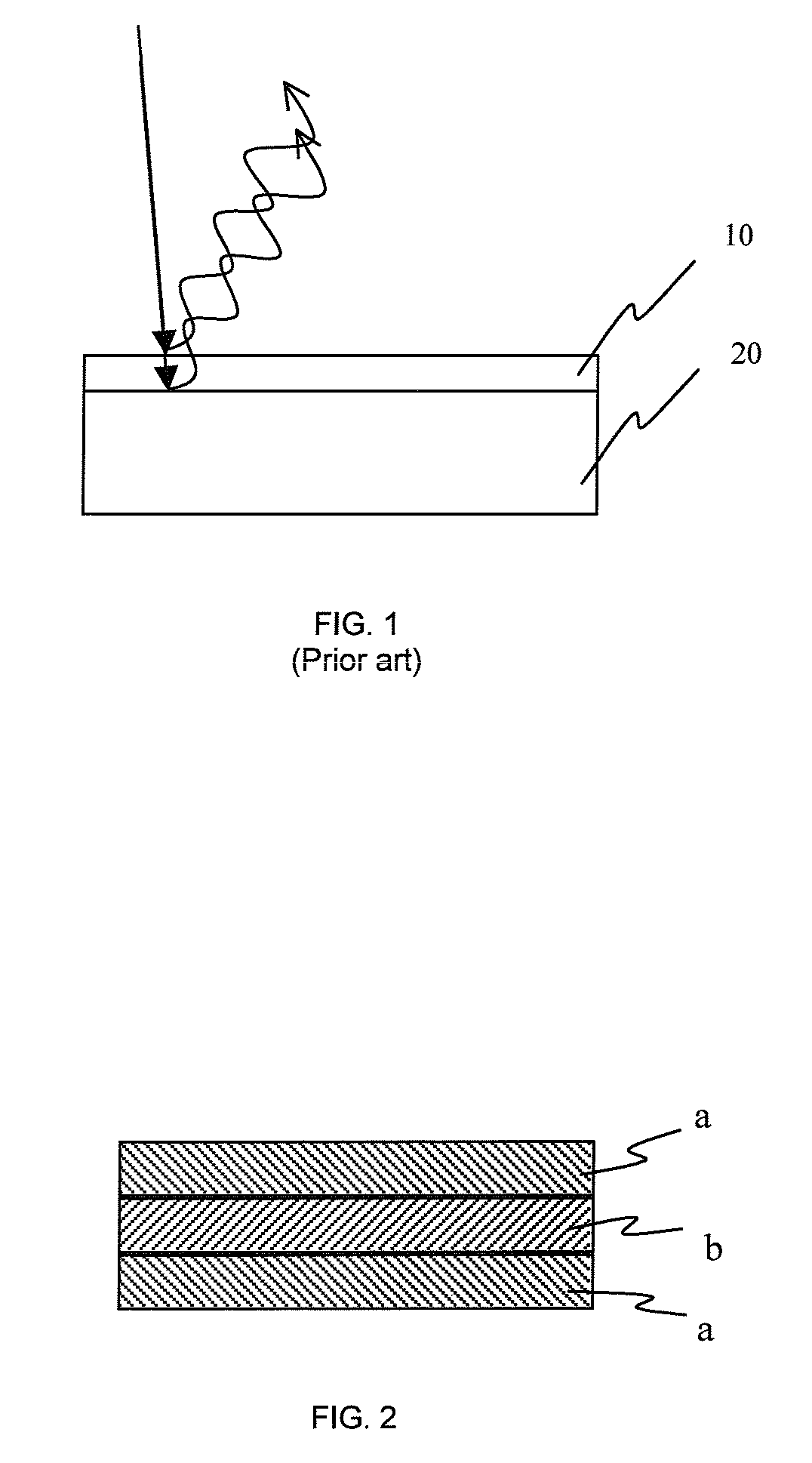
[0037]For example, referring to prior art FIG. 1, a thin film layer 10 having a refractive index n1 is shown on a substrate 20 having a refractive index n2. With n1 less than n2, and with the n1 and the thickness of the thin film layer d1 selected to provide an optical thickness equal to a quarter wave of the incident radiation λ, the light reflected from the air / thin-film and the thin-film / substrate interfaces will be exactly 180 degrees out of phase. This 180 degree phase...


PUM


Abstract

Thin-film coatings, which for example have alternating layers of high and low refractive index materials, are shown to function as both positive and negative C-plates, in dependence upon the incident radiation. In particular, the shape of the retardance versus angle of incidence profile is found to be determined, at least in part, by the phase thickness of the thin film coating (i.e., the optical thickness in terms of the wavelength of the incident radiation, which may, for example, be expressed in degrees, radians, or as the number of quarter wavelengths). These thin film coatings are optionally integrated into anti-reflection coatings, thin film interference filters and / or other components to improve efficiency and / or functionality.

Description

CROSS-REFERENCE TO RELATED APPLICATIONS[0001]This application claims priority from U.S. Provisional Application No. 60 / 803,735 filed Jun. 2, 2006 and U.S. Provisional Application No. 60 / 823,326 filed Aug. 23, 2006, both of which are hereby incorporated by reference.MICROFICHE APPENDIX[0002]Not Applicable.TECHNICAL FIELD[0003]The present application relates generally to thin films, and in particular, to thin-film coatings designed for providing a positive and / or a negative C-plate component.BACKGROUND OF THE INVENTION[0004]The use of thin films in anti-reflection coatings and interference filters is well known. With regard to the former, the thickness and refractive index of the one or more thin film layers is selected to decrease light reflected from a substrate. With regard to the latter, the thickness, refractive index, and / or number of layers is selected to provide the desired filter properties.[0005]More recently, there has been increasing interest in using thin films to provide...

Claims


Application Information

Patent Timeline
Patent Type & Authority Patents(United States)
IPC IPC(8): G02B1/10
CPCG02B5/3016G02B5/3083
Inventor HENDRIX, KAREN D.TAN, KIM L.
Owner VIAVI SOLUTIONS INC
Why Eureka
Try Eureka