Zoom lens system and electronic image pickup apparatus using the same

a technology of electronic image pickup and zoom lens, which is applied in the direction of optics, instruments, optical elements, etc., can solve the problems of difficult to constitute the zoom lens system to be thin, shorten the focal length,

Inactive Publication Date: 2006-12-21
OLYMPUS CORP
View PDF9 Cites 68 Cited by
  • Summary
  • Abstract
  • Description
  • Claims
  • Application Information

AI Technical Summary

Benefits of technology

[0011] The present invention provides a zoom lens system whic

Problems solved by technology

However, in the zoom lens system for use in the digital camera including a small image sensor, a f

Method used


Image

  • Zoom lens system and electronic image pickup apparatus using the same
  • Zoom lens system and electronic image pickup apparatus using the same
  • Zoom lens system and electronic image pickup apparatus using the same

Examples


example 1

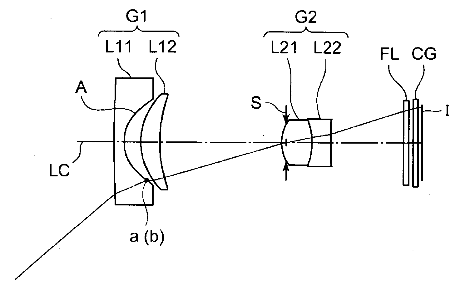
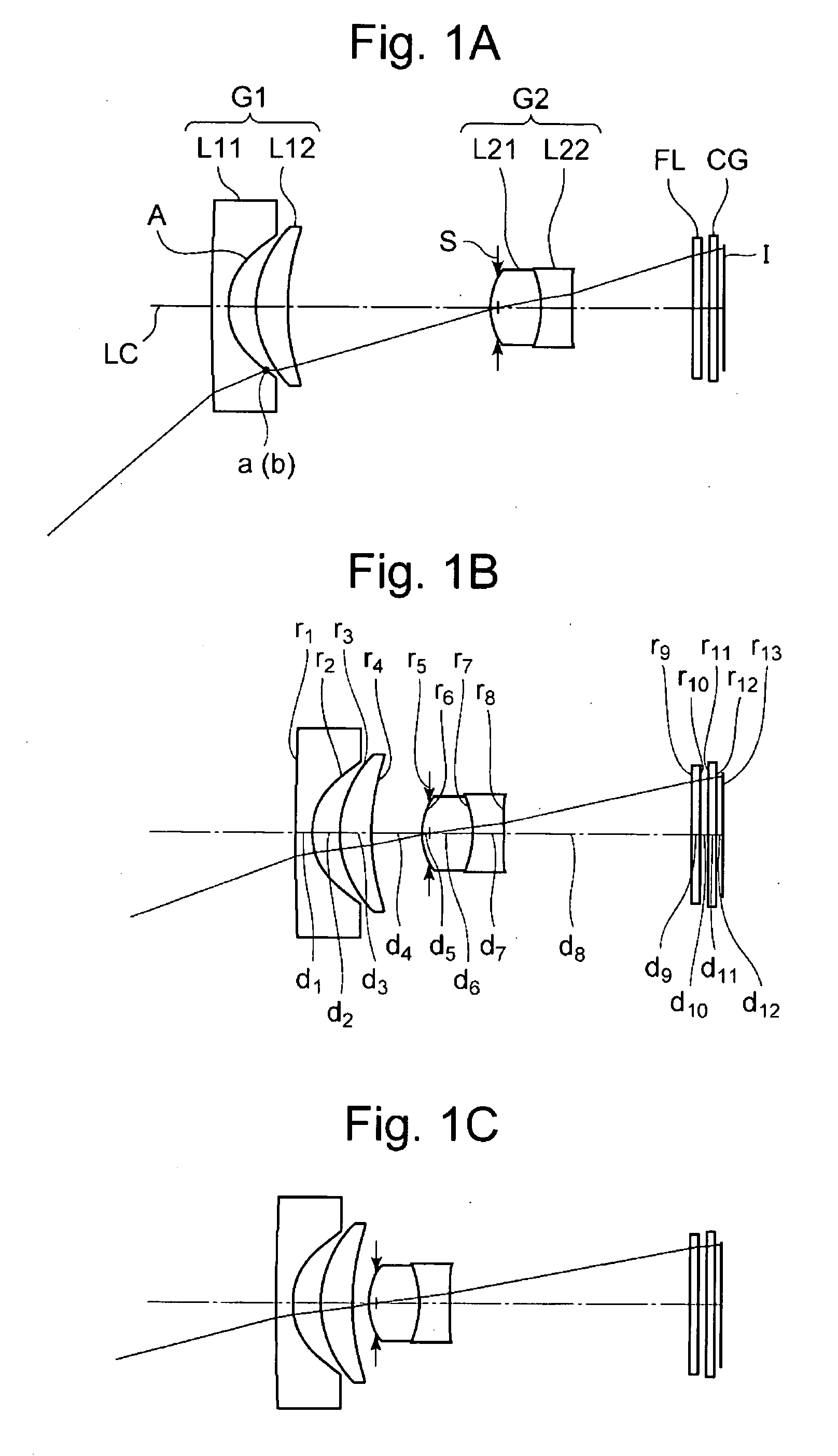
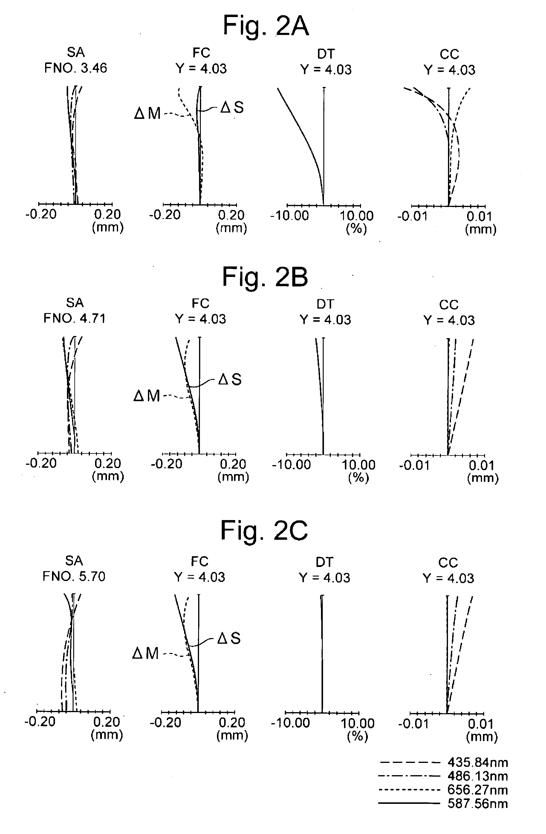
[0196]FIGS. 1A to 1C show sectional views along an optical axis, showing an optical constitution of a zoom lens system in Example 1 of the present invention, FIG. 1A shows a state in a wide-angle end, FIG. 1B shows an intermediate state, and FIG. 1C shows a state in a telephoto end. FIGS. 2A to 2C are diagrams showing a spherical aberration SA, an astigmatism FC, a distortion DT and a chromatic aberration CC of magnification when the zoom lens system is focused on an infinite object in Example 1, FIG. 2A shows a state in the wide-angle end, FIG. 2B shows an intermediate state, and FIG. 2C shows a state in the telephoto end.

[0197] As shown in FIGS. 1A to 1C, the zoom lens system of Example 1 is constituted of, in order from an object side toward an image pickup surface I, a first lens unit G1 having a negative refractive power and a second lens unit G2 having a positive refractive power. In the drawings, S denotes an aperture stop, FL denotes a parallel flat plate such as a low pass...

example 2

[0210]FIGS. 3A to 3C show sectional views along an optical axis, showing an optical constitution of a zoom lens system in Example 2, FIG. 3A shows a state in a wide-angle end, FIG. 3B shows an intermediate state, and FIG. 3C shows a state in a telephoto end. FIGS. 4A to 4C are diagrams showing a spherical aberration SA, an astigmatism FC, a distortion DT and a chromatic aberration CC of magnification when focused on an infinite object in Example 2, FIG. 4A shows a state in the wide-angle end, FIG. 4B shows an intermediate state, and FIG. 4C shows a state in the telephoto end.

[0211] As shown in FIGS. 3A to 3C, the zoom lens system of Example 2 is constituted of, in order from an object side toward an image pickup surface I, a first lens unit G1 having a negative refractive power and a second lens unit G2 having a positive refractive power. In the drawings, S denotes an aperture stop, FL denotes a parallel flat plate such as a low pass filter or an infrared absorptive filter, CG deno...

example 3

[0221]FIGS. 5A to 5C show sectional views along an optical axis, showing an optical constitution of a zoom lens system in Example 3, FIG. 5A shows a state in a wide-angle end, FIG. 5B shows an intermediate state, and FIG. 5C shows a state in a telephoto end. FIGS. 6A to 6C are diagrams showing a spherical aberration SA, an astigmatism FC, a distortion DT and a chromatic aberration CC of magnification when focused on an infinite object in Example 3, FIG. 6A shows a state in the wide-angle end, FIG. 6B shows an intermediate state, and FIG. 6C shows a state in the telephoto end.

[0222] As shown in FIGS. 5A to 5C, the zoom lens system of Example 3 is constituted of, in order from an object side toward an image pickup surface I, a first lens unit G1 having a negative refractive power and a second lens unit G2 having a positive refractive power. In the drawings, S denotes an aperture stop, FL denotes a parallel flat plate such as a low pass filter or an infrared absorptive filter, CG deno...


PUM


Abstract

A zoom lens system comprising, in order from an object side: a first lens unit comprising two lens components; and a second lens unit comprising one lens component, during zooming, a space between the first lens unit and the second lens unit changing, the first lens unit and the second lens unit having aspherical surfaces, at least one aspherical surface of the first lens unit satisfying the following condition:
R1/h1<1.35,
wherein R1 denotes a paraxial radius of curvature of the at least one aspherical surface, and h1 denotes a length from a first intersection between a chief ray reaching a point of maximum image height on an image surface and the at least one aspherical surface to an optical axis in the wide-angle end at a time when the chief ray enters the zoom Lens system with an angle of incidence equal to or larger than 36 degrees and passes through the at least one aspherical surface.

Description

CROSS REFERENCE TO RELATED APPLICATIONS [0001] This application claims benefit under 35 U.S.C. sec. 119 of Japanese patent applications of No. 2005-176,764 filed in Japan on Jun. 16, 2005 and No. 2005-263,582 filed in Japan on Sep. 12, 2005, the contents of which are incorporated herein by reference. BACKGROUND OF THE INVENTION [0002] 1. Field of the Invention [0003] The present invention relates to a zoom lens system-and an electronic image pickup apparatus using the same. [0004] 2. Description of the Related Art [0005] In recent years, it has been general to mount a zoom lens system as a photographing lens on an electronic image pickup apparatus such as a digital camera. Moreover, to miniaturize an electronic image pickup apparatus such as the digital camera, there has further risen a demand for thinning of the zoom lens system as the photographing lens. [0006] However, in the zoom lens system for use in the digital camera including a small image sensor, a focal length shortens. T...

Claims


Application Information

Patent Timeline
IPC IPC(8): G02B15/14
CPCG02B15/177G02B15/143507
Inventor WATANABE, MASAHITOAMANAI, TAKAHIRO
Owner OLYMPUS CORP
Why Eureka
Try Eureka