AI technical title is built by Patsnap AI team. It summarizes the technical point description of the patent document.
a technology of arm slings and slings, applied in the field of arm slings, can solve problems such as difficulty in installation
Inactive Publication Date: 2010-12-21
BROOKS LUCILLE S
View PDF15 Cites 0 Cited by
Summary
Abstract
Description
Claims
Application Information
AI Technical Summary
This helps you quickly interpret patents by identifying the three key elements:
Problems solved by technology
Method used
Benefits of technology
Problems solved by technology
These slings are sometimes referred to as “open top-closed elbow” slings which can be difficult to install and somewhat dangerous as a patient's arm inadvertently can fall out of the prior art sling.
Method used
Image
Click on the blue label to locate the original text in one second.
Reading with bidirectional positioning of images and text.
Examples
Embodiment Construction
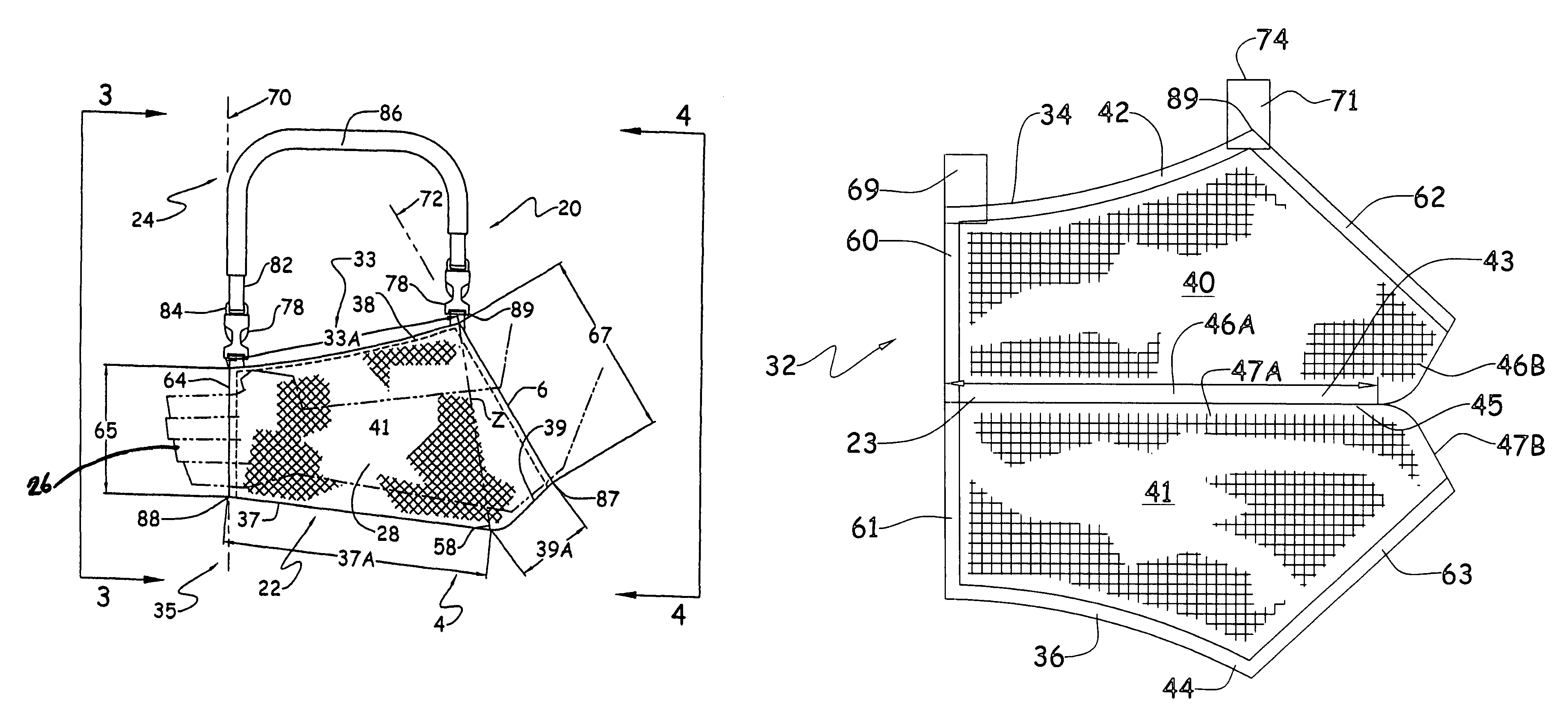
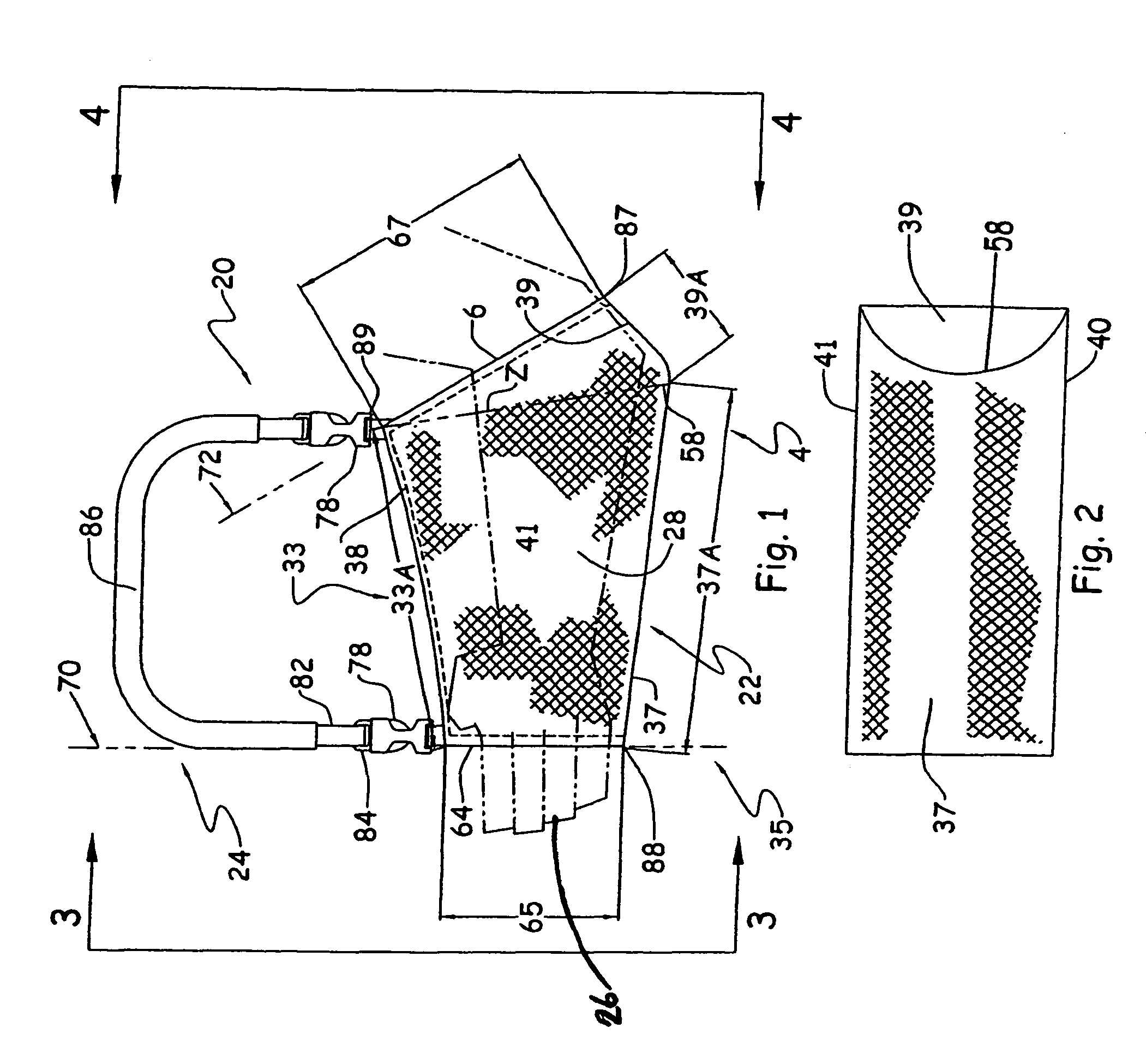
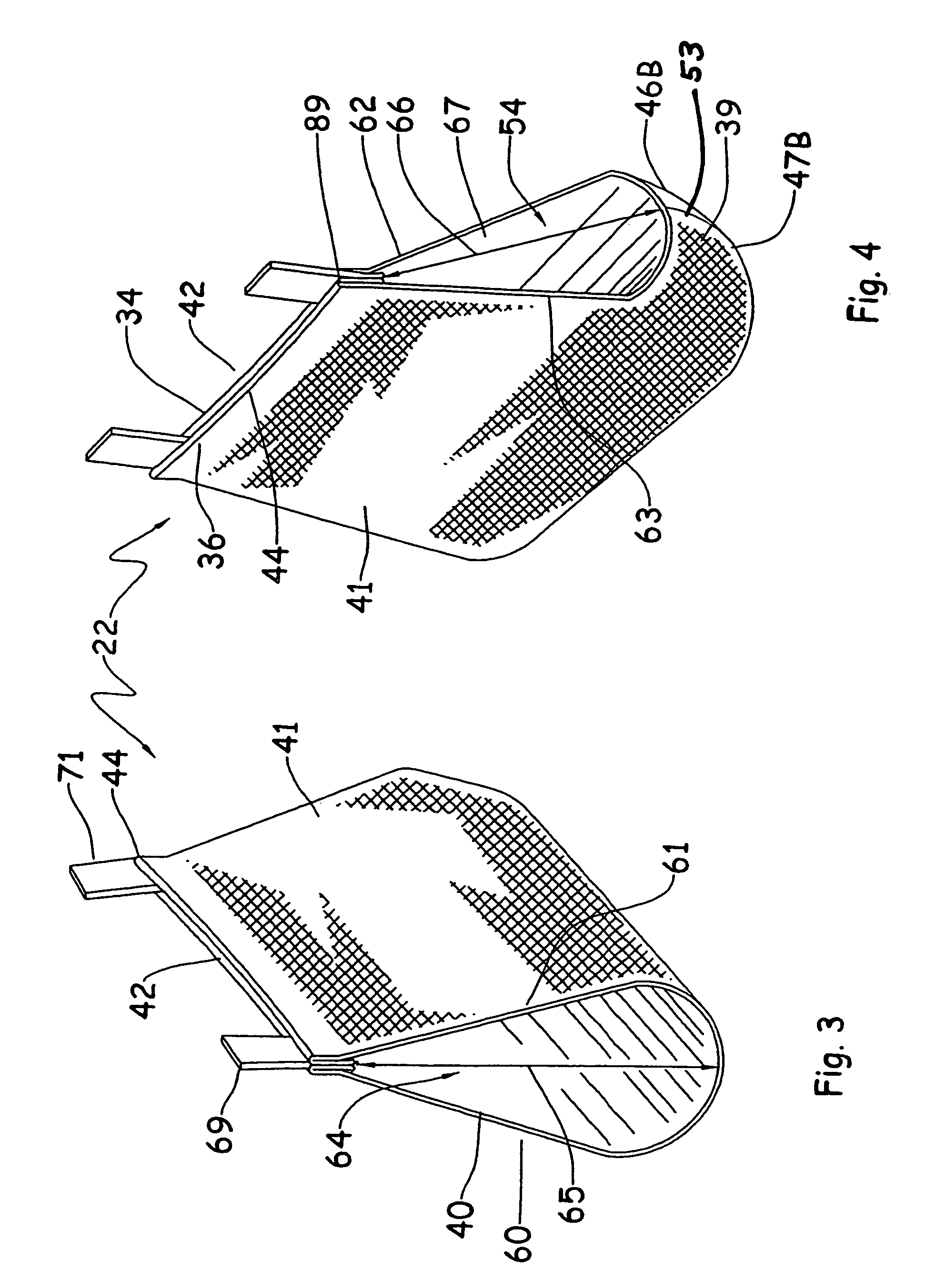
[0021]An arm sling, generally designated 20, includes a tubular arm support 22 and a neck strap 24, for detachably receiving a patient's arm, generally illustrated in chain lines at 26. The tubular arm support 22 is fabricated from a single sheet 32 of pliable material, such as cotton cloth, which is cut along the pattern illustrated in FIG. 5 to provide two identical panels 40 and 41 which are then folded about a fold line 23 to the confronting positions illustrated in FIG. 7 or rolled into a tubular configuration as illustrated in FIGS. 1-4 with the free terminal edge portions, generally designated 34 and 36, disposed in confronting relation and sewn or otherwise coupled together along an upper stitch line 38 to provide an upper border 33 of a predetermined length 33A and a lower border, generally designate 35, of a substantially greater length. The lower border 35 includes a forward lower border portion 37 of a predetermined length 37A which is greater than the upper border lengt...
PUM
Abstract
An arm sling and method of making an arm sling including an open ended arm receiving tube supported on a patient's neck via a neck strap. The tube includes a forward end portion with an open front end of predetermined size and a rear end portion having an elbow receiving pocket adjacent an enlarged diameter rear opening. The arm receiving tube is formed from a single sheet of pliable fabric and includes first and second elongate opposing substantially identical side wall panels each having upper and lower edges spanning front and rear edges which form the front and rear openings. Each lower edge includes a front lower edge portion longer than the upper edge and a rear lower edge portion which is shorter than the upper edge. The rear lower edge portion is upwardly inclined relative to the front lower edge and has a rear end terminating in the lower end of the rear edge.
Description
BACKGROUND OF THE INVENTION[0001]1. Field of the Invention[0002]This invention relates to an arm sling and more particularly to a new and improved tubular arm sling.[0003]2. Description of Prior Art and Objects[0004]Arm slings have been provided heretofore such as that illustrated in U.S. Pat. No. 2,088,927 issued to D. Roy on Aug. 3, 1937, U.S. Pat. No. 4,572,172 issued to L. Benton Williams on Feb. 25, 1986 and U.S. Pat. No. 6,110,133 issued to Graham Douglas Ritts on Aug. 29, 2000. These slings are sometimes referred to as “open top-closed elbow” slings which can be difficult to install and somewhat dangerous as a patient's arm inadvertently can fall out of the prior art sling.[0005]Other prior art slings such as those illustrated in U.S. Pat. No. 1,266,688 issued to J. C. Kassner on May 21, 1918, U.S. Pat. No. 5,358,470 issued to James Johnson on Oct. 25, 1994, U.S. Pat. No. 1,621,323 issued to E. M. Horn on Aug. 21, 1926; U.S. Pat. No. 6,595,936 B1 issued to Olarewaju J. Oladip...
Claims
Application Information
Patent Timeline
Application Date:The date an application was filed.
Publication Date:The date a patent or application was officially published.
First Publication Date:The earliest publication date of a patent with the same application number.
Issue Date:Publication date of the patent grant document.
PCT Entry Date:The Entry date of PCT National Phase.
Estimated Expiry Date:The statutory expiry date of a patent right according to the Patent Law, and it is the longest term of protection that the patent right can achieve without the termination of the patent right due to other reasons(Term extension factor has been taken into account ).
Invalid Date:Actual expiry date is based on effective date or publication date of legal transaction data of invalid patent.

