
Sensor glove

a technology of sensors and gloves, applied in the field of sensors gloves, can solve the problems of limited early application of gloves in servi

Inactive Publication Date: 2011-01-04
BARCLAY DAVID +1
View PDF3 Cites 148 Cited by
  • Summary
  • Abstract
  • Description
  • Claims
  • Application Information

AI Technical Summary

Benefits of technology

[0014]A combination of potentiometers and flex sensors are mounted on a flexible fabric base coupled to a reference unit, to generate signals in response to the movement or articulation of a hand or individual fingers or joints that are in contact with the fabric, resulting in an organic composite movement for creating performances in motion, sound and light, in response to the movement of the fingers and hand within the glove worn by an artist, a performer or a puppeteer with the skill necessary to produce an animated performance for viewing in and for film or video media. The performer uses the transducer like a musician playing a musical instrument.

Problems solved by technology

Bulky wiring, and a limited application for the analogue output of potentiometers limited the early application of the gloves in service, and because of high maintenance requirements.

Method used


Image

  • Sensor glove
  • Sensor glove
  • Sensor glove

Examples


Embodiment Construction

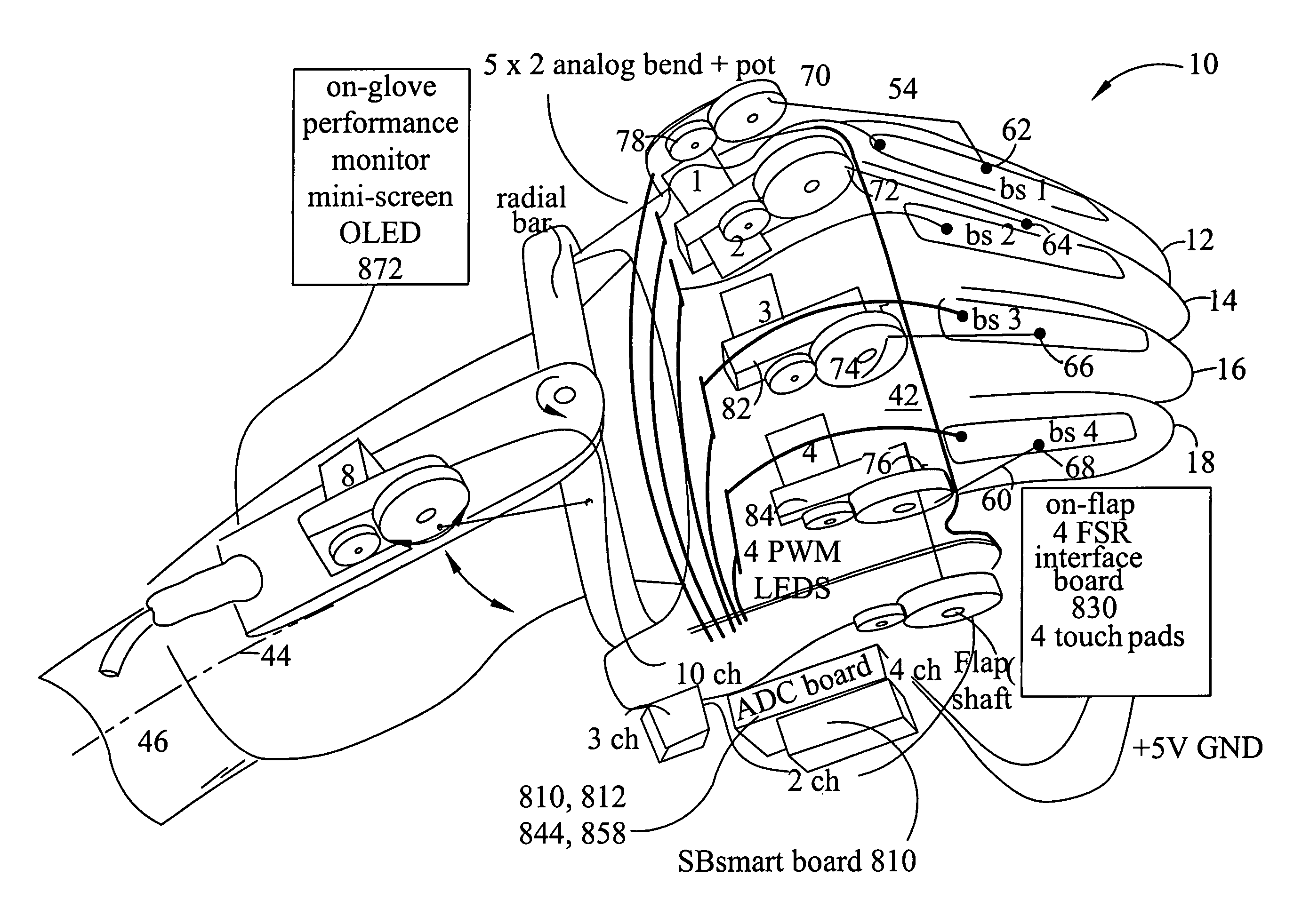
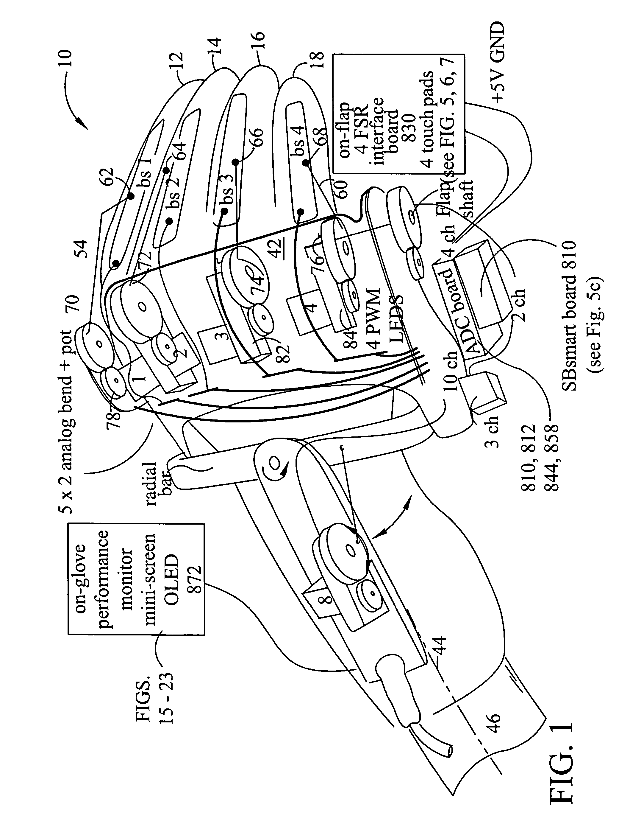
[0037]FIG. 1 shows the sensor glove 10 in a perspective view as it is worn on the fingers and hand of a performer (not shown). The sensor glove 10 is used to provide signals representing the motion of one or more fingers, shown generally as 12, 14, 16, 18 and a thumb, (not shown) in relation to the rigid reference base 42.

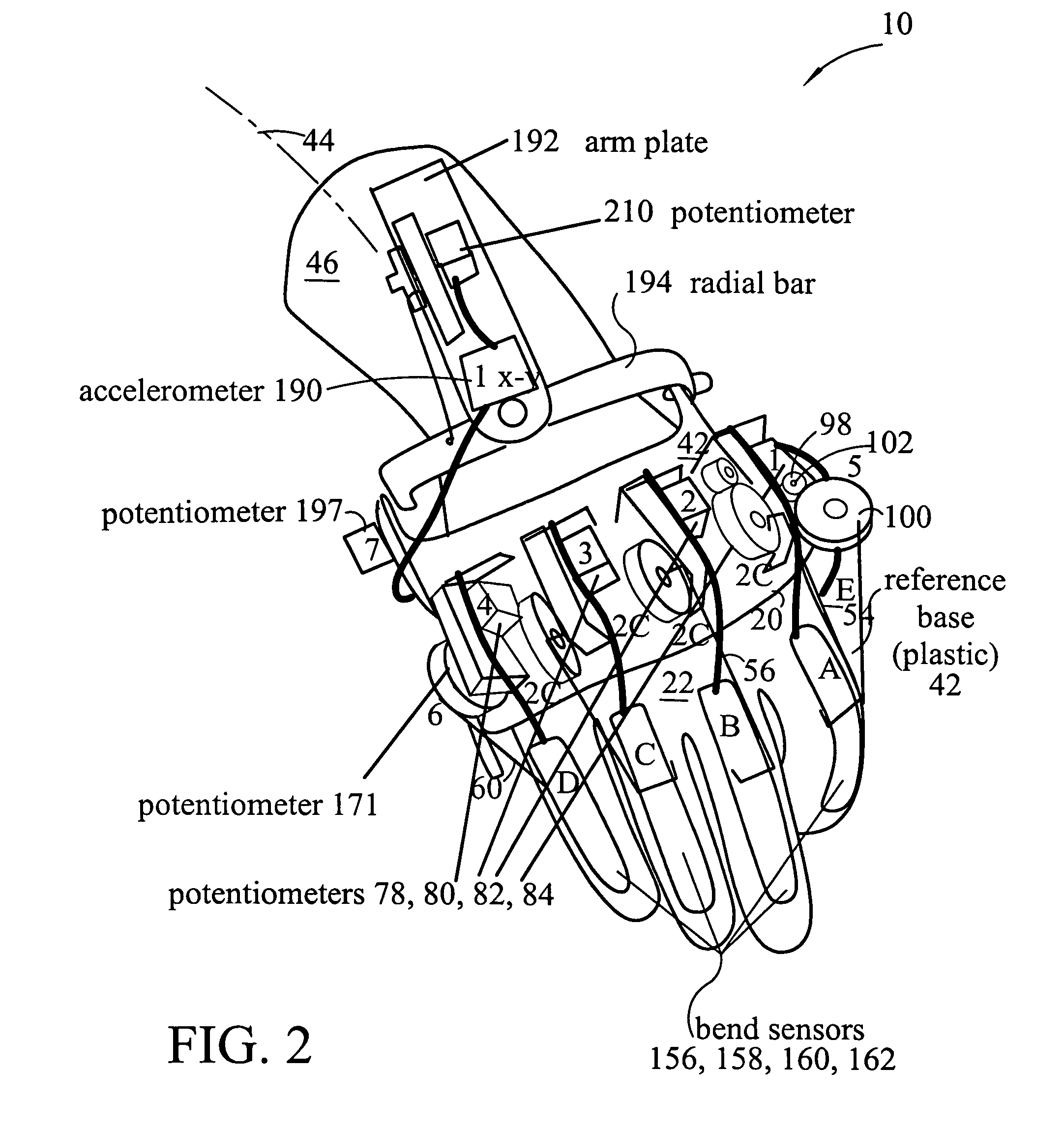
[0038]FIG. 2 shows the rigid reference base 42 coupled to the top or dorsal surface of the palmer region 22 of the sensor glove 10. The sensor glove 10 has a palmer region shown within the limits of a bracket 26, shown on FIG. 13 and discussed above in connection with the Background.

[0039]Bracket 28 shows the limits of a finger region which locates the glove fingers or the fingers of the glove. With reference to FIGS. 3, 4 and 13, the finger region extends from the metacarpalphalangeal joint 337, 338, 339 and 340 to the finger tip.

[0040]On FIG. 13, phantom line 32 passes through the metacarpalphalangeal joint 337, 338, 339 and 340 to characterize the location of th...


PUM


Abstract

A Sensor glove is an instrument, in the same way that a piano is an instrument. The Sensor glove is purchased and the owner then learns to use it and the sensors therein to develop the performance of a sound, character or model, or to “conduct” or “play” the sensor movements and experience the response of the model in real time. Several performers with a number of the Sensor glove can control over 200 motors or hundreds of control points on a character at one time, manipulate audio data, or computer images etc. The characteristics of the sensors on the gloves can be adjusted to the needs and demands of the wearer or the many performer and wearers in those venues where multiple performers are used with many gloves to control or produce the motions and sounds of many distinct characters in a screen play.

Description

[0001]This non-provisional application claims priority from Provisional Patent Application Ser. No. 60 / 706,627 filed Aug. 8, 2005 for a Sensor Glove and having common inventors and assignees.FIELD OF THE INVENTION[0002]Motion Control and Animation—primary markets; film and television production, computer game industry, motion capture. An input device designed to allow the user direct interface via a computer with a real time tactile experience, i.e. joysticks, face-tracking headsets. A hand covering in the form of a glove, and used for the control of motion, sound and light.BACKGROUND OF THE INVENTION[0003]First sensor glove was created in 1991, using potentiometers, for the animatronic company Ultimate Animates, based in Hertfordshire, England. The gloves were used for controlling animatronic servo motors such as those used in connection with puppet characters that appeared in movies and for the TV industry. The inventor of the first gloves used at that time was common with and to ...

Claims


Application Information

Patent Timeline
Patent Type & Authority Patents(United States)
IPC IPC(8): A61B5/103B25J3/00B25J1/00A61H1/02A61H1/00A61B5/117A61H5/00B25J13/08B25J3/04B25J19/00B25J15/00
CPCA61B5/6806G06F3/014A61B5/11
Inventor BARCLAY, DAVIDSILVER, GLENNVERSTEEGH, JOHANLANOIL, BRUCE
Owner BARCLAY DAVID
Learn More