Force or pressure sensor and method for applying the same
What is AI technical title?
AI technical title is built by Patsnap AI team. It summarizes the technical point description of the patent document.
a force or pressure sensor technology, applied in the field of force or pressure sensors, can solve the problems of sensor static resistance to pressure relatively modest, sensor remains comparatively low in responsivity, sensor is not structurally designed to provide simultaneously a high load rating and a high sensitivity, etc., and achieves the effect of high load rating
Inactive Publication Date: 2011-01-04
APPLE INC
View PDF13 Cites 81 Cited by
Summary
Abstract
Description
Claims
Application Information
AI Technical Summary
This helps you quickly interpret patents by identifying the three key elements:
Problems solved by technology
Method used
Benefits of technology
Problems solved by technology
Since the piezocrystal is compressed and its surface area is relatively small, the sensor remains comparatively low in responsivity.
The sensor is not structurally designed to provide simultaneously a high load rating and a high sensitivity.
Since some of the sensor's housing structure consists of a piezoelement, the sensor's static resistance to pressure is relatively modest.
This sensor is not capable of handling major external loads, either.
Method used
Image
Click on the blue label to locate the original text in one second.
Reading with bidirectional positioning of images and text.
Examples
Embodiment Construction
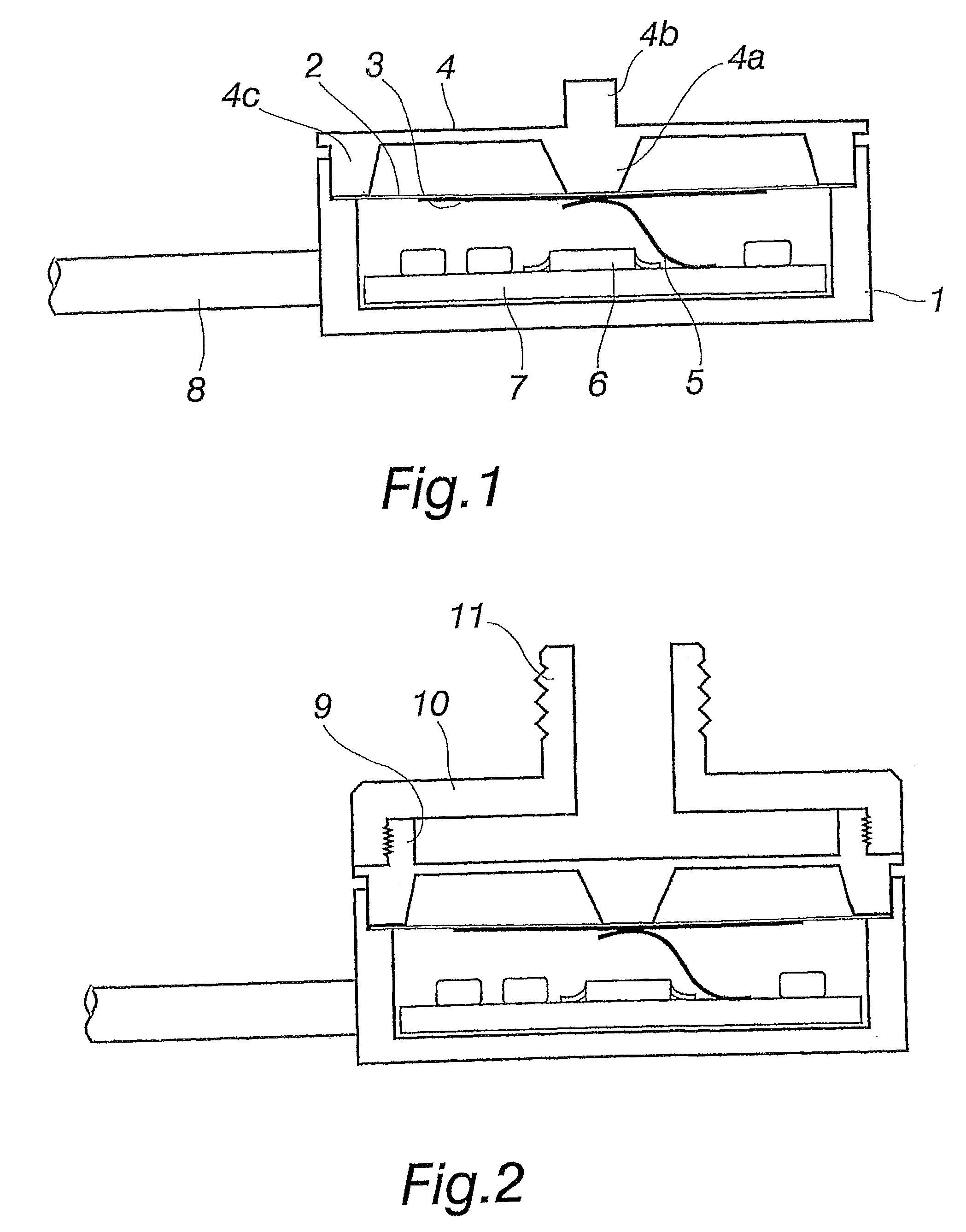
[0016]The sensor to be described hereinafter has properties like a high resistance to force or pressure, a high sensitivity, a trouble-free operation, a simplicity of required electronics, and a broad frequency repetition. Surprisingly, all these qualities are achieved with a sensor assembly to be described hereinbelow.
[0017]A sensor frame 1 is substantially rigid and resistant to mechanical loading. Therefore, the frame 1 is made e.g. from stainless steel. A sensor cover 4 is also substantially rigid and resistant to mechanical loading, and preferably made from stainless steel or another suitable metal. The frame 1 and the cover 4 are metal blocks in the shape of bodies of revolution. They can also be made of a plastic or composite material or some other rigid, durable material. The actual sensor element comprises a piezoelectric ceramic diaphragm 3, which is applied to a thin, flexible metal diaphragm 2. The flexible metal diaphragm is in turn attached by its peripheral rim betwee...
PUM
Property
Measurement
Unit
diameter
aaaaa
aaaaa
diameter
aaaaa
aaaaa
flexible
aaaaa
aaaaa
Abstract
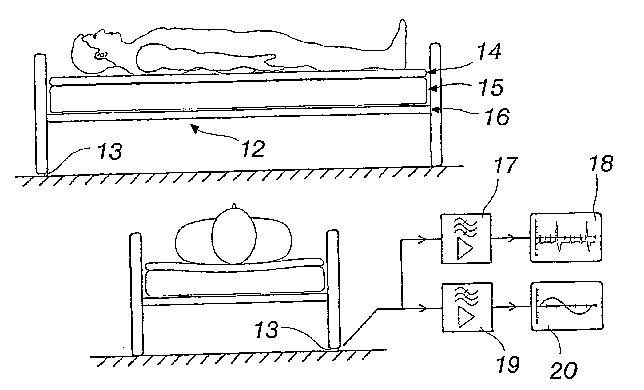
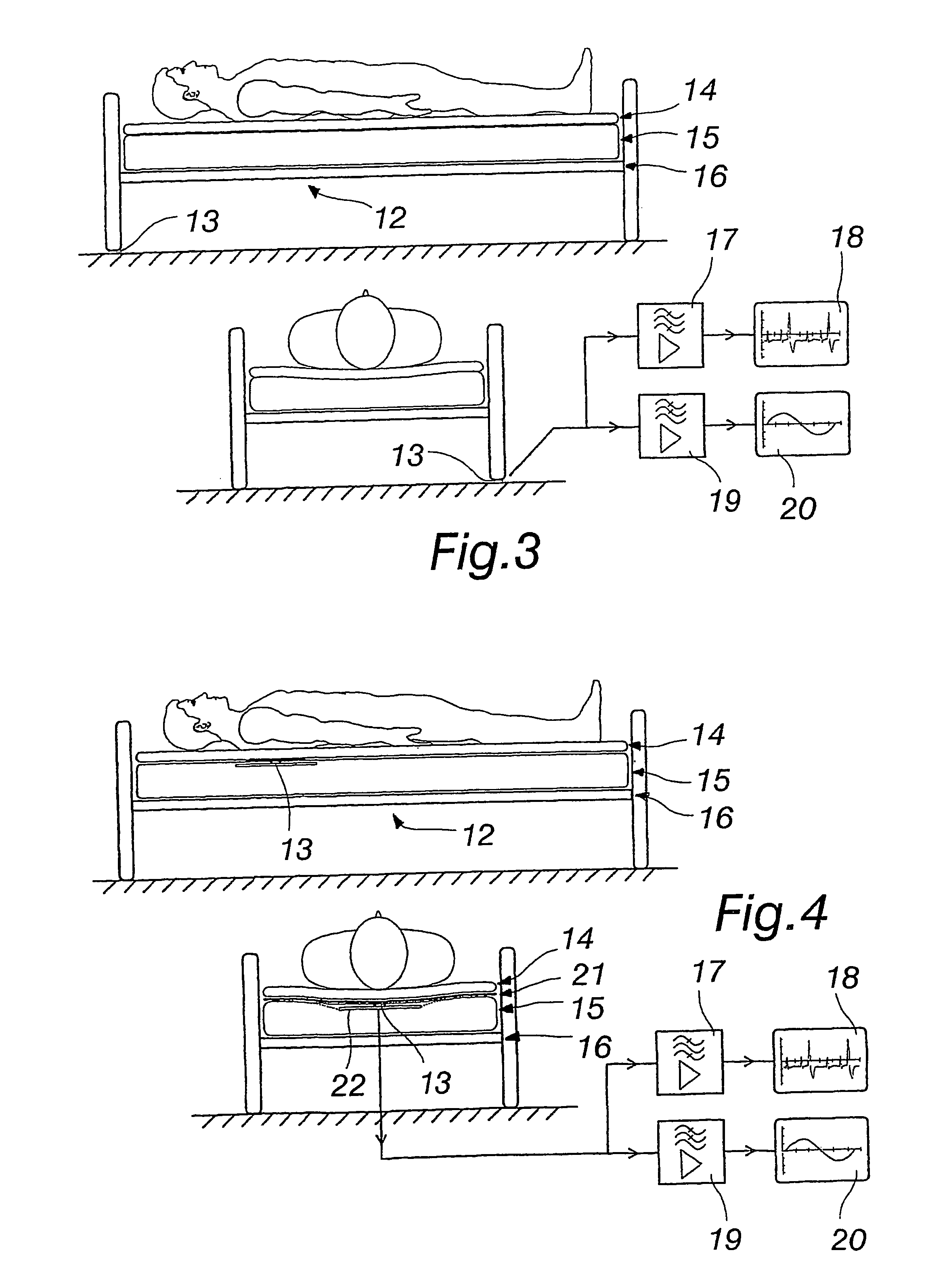
The invention relates to a force or pressure sensor and a method for applying the same. The pressure sensor includes a substantially rigid, mechanical-load resistant frame, a flexible diaphragm secured over its peripheral rim to the frame, and a piezoelectric sensor diaphragm applied to the surface of the flexible diaphragm. The sensor diaphragm loading element comprises a substantially rigid, mechanical-load resistant cover, having its protrusion or shoulder bearing against a middle section of the flexible diaphragm and thereby prestressing the flexible diaphragm and the piezoelectric sensor diaphragm attached thereto. The frame and the cover define therebetween a closed, hermetically sealed housing chamber, the flexible diaphragm and the piezoelectric sensor diaphragm located thereinside. The placement of one or more responsive, yet load-resistant sensors in contact with a bed enables measuring a sleeping or lying person for his or her heart rate and respiratory amplitude, as well as frequency.
Description
REFERENCE TO RELATED APPLICATION[0001]This application is a divisional of application Ser. No. 10 / 525,703, filed Feb. 18, 2005, pending, which is a national stage of PCT / FI03 / 00604, filed Aug. 15, 2003, the disclosure of which is incorporated herein by reference.BACKGROUND OF THE INVENTION[0002]The invention relates to a force or pressure sensor, comprising a substantially rigid, mechanical-load resistant frame, a flexible diaphragm secured over its peripheral rim to the frame, and a piezoelectric sensor diaphragm applied to the surface of the flexible diaphragm.[0003]The invention relates also to a method for applying this method, such that a sleeping or lying person can be measured for his or her heart rate and respiratory amplitude, as well as frequency.[0004]Patent publications U.S. Pat. Nos. 4,570,097 , 4,567,395, 4,590,400 and 5,353,633 disclose a piezoelectric pressure sensor for measuring changes of a cylinder pressure in an internal combustion engine during ignition. The cy...
Claims
Application Information
Patent Timeline
Application Date:The date an application was filed.
Publication Date:The date a patent or application was officially published.
First Publication Date:The earliest publication date of a patent with the same application number.
Issue Date:Publication date of the patent grant document.
PCT Entry Date:The Entry date of PCT National Phase.
Estimated Expiry Date:The statutory expiry date of a patent right according to the Patent Law, and it is the longest term of protection that the patent right can achieve without the termination of the patent right due to other reasons(Term extension factor has been taken into account ).
Invalid Date:Actual expiry date is based on effective date or publication date of legal transaction data of invalid patent.

