
Image forming apparatus

a technology of forming apparatus and forming plate, which is applied in the direction of printing mechanism, power drive mechanism, printing, etc., can solve the problems of reducing image quality, deformation or breakage of arms, excessive torque acting on arms, etc., and achieves smooth upward movement, without excessive load

Inactive Publication Date: 2011-01-11
KYOCERA DOCUMENT SOLUTIONS INC
View PDF9 Cites 2 Cited by
  • Summary
  • Abstract
  • Description
  • Claims
  • Application Information

AI Technical Summary

Benefits of technology

The present invention relates to an image forming apparatus with a conveyance unit and elevator for smoothly moving the conveyance unit upward and downward without generating excessive loads. The elevator includes an eccentric cam and the conveyance unit has a contact surface to be held in contact with the eccentric cam. The conveyance unit is moved upward and downward by the rotation of the eccentric cam. The invention also includes a positioning member for positioning the conveyance unit and a guiding mechanism for guiding vertical movements of the conveyance unit. The technical effect of the invention is to enable smooth movement of the conveyance unit without excessive loads.

Problems solved by technology

However, since the relatively long arms extend from the supporting shaft in such an elevator for the platen unit, excessive torques might act on the arms themselves, the supporting shaft and a driving device such as a motor.
This might possibly cause the arms and the motor to be deformed or broken.
Therefore, problems of reducing image quality and shortening the life of the apparatus occur.

Method used


Image

  • Image forming apparatus
  • Image forming apparatus
  • Image forming apparatus

Examples


first embodiment

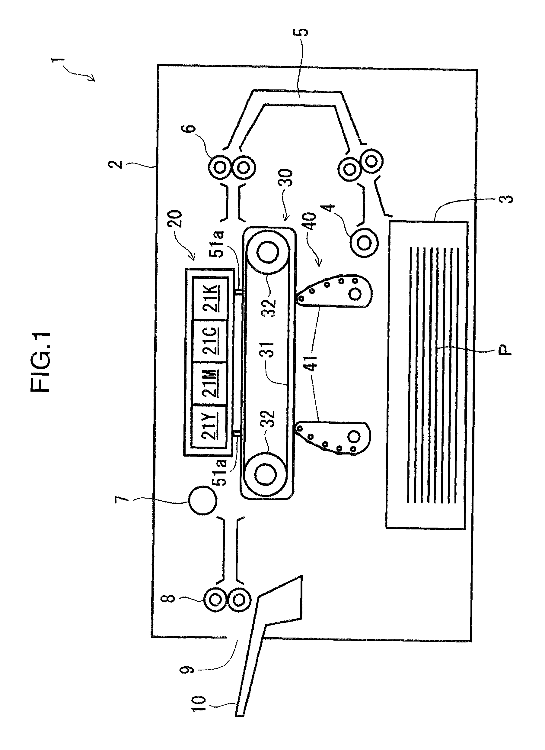
[0030]First of all, an image output operation is described while the construction of the image forming apparatus according to embodiments of the present invention is briefly described with reference to FIG. 1. FIG. 1 is a diagrammatic front view in section of an ink-jet printer 1 according to a first embodiment of the invention.

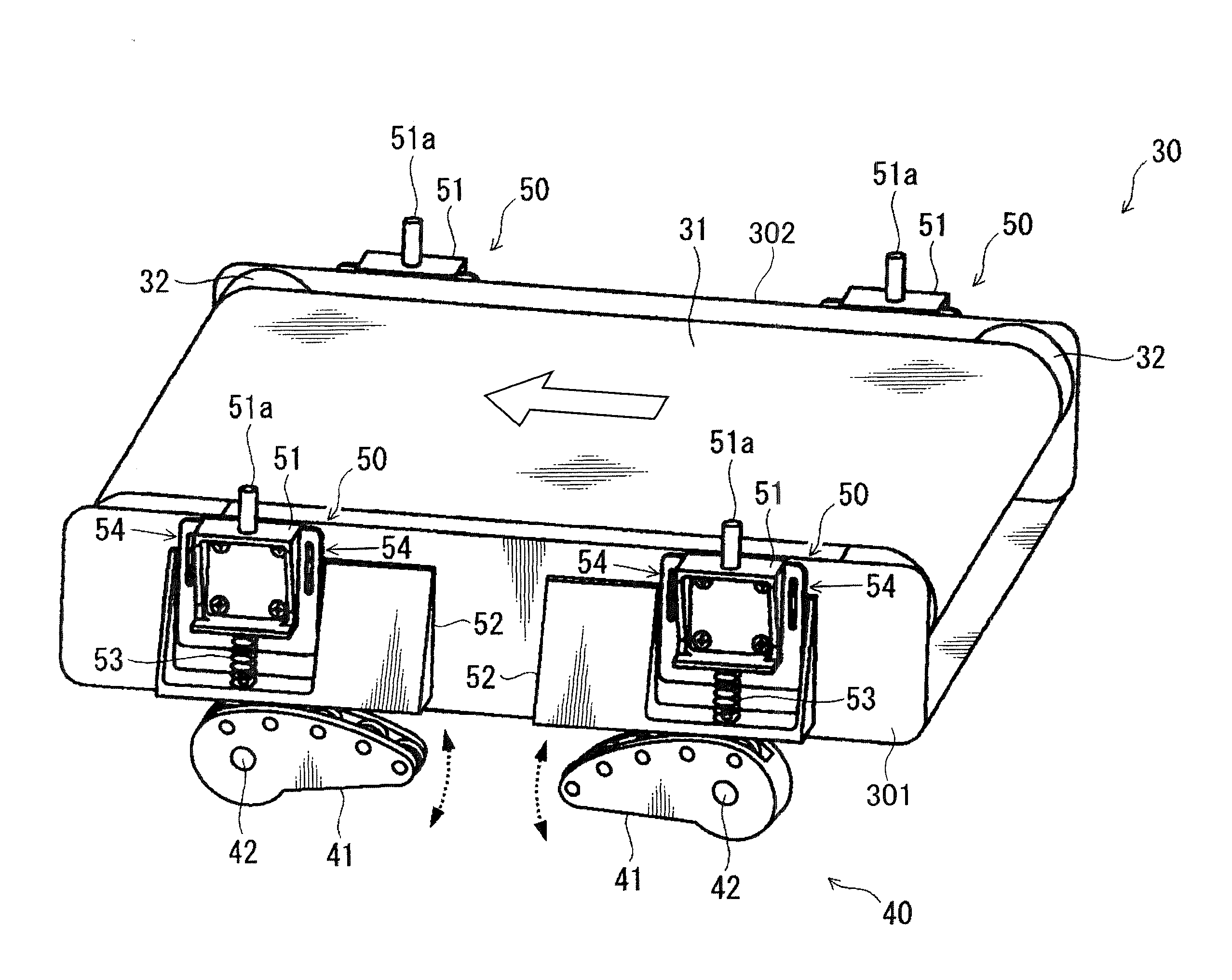
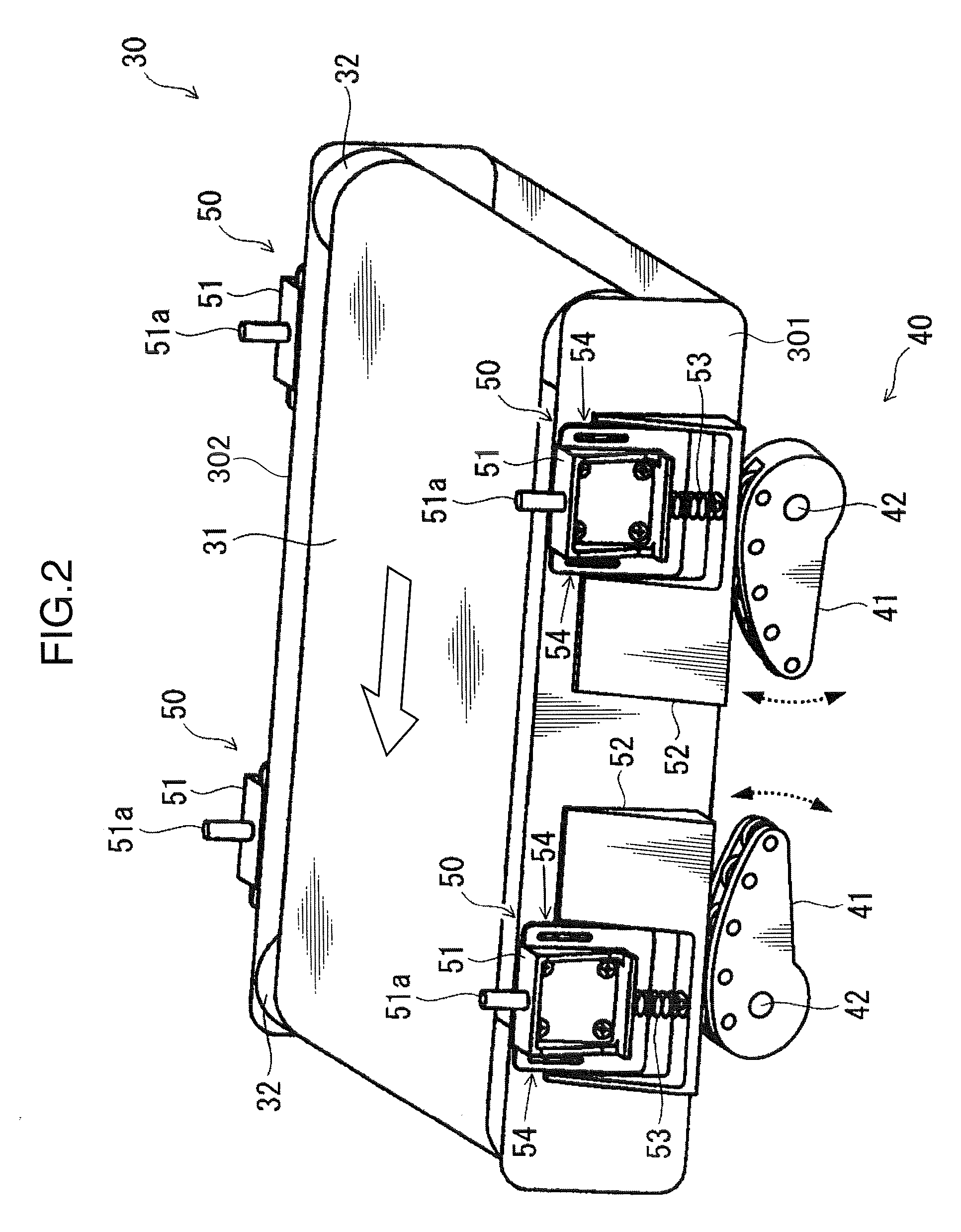
[0031]The printer 1 is provided with a recording device 20 accommodated in an apparatus main body 2 having a box structure and adapted to print a color ink image on a sheet P (an example of recording medium), a conveyance unit 30 arranged below the recording device 20 to face it and adapted to convey the sheet P, and an elevator 40 for moving the conveyance unit 30 upward and downward. The printer 1 is additionally provided with a sheet cassette 3, a sheet feeder 4, a sheet conveyance path 5, registration rollers 6, a dryer 7, discharge rollers 8, a discharge port 9 and a discharge tray 10.

[0032]The sheet cassette 3 is arranged at the bottom in the interior o...

second embodiment

[0075]FIG. 11 is a diagrammatic front view in section of an ink-jet printer 1A according to a second embodiment of the present invention. A point of difference from the first embodiment is that guiding mechanisms 60 are provided to prevent displacements of the conveyance unit 30 in transverse direction upon moving the conveyance unit 30 upward and downward. Parts in FIGS. 11, 12 to 19 identified by the same reference numerals as in FIGS. 1 to 10 described above are identical and described either not at all or only briefly.

[0076]FIG. 12 is a perspective view of the conveyance unit 30 and the elevator 40 provided with the guiding mechanisms 60, and FIG. 13 is a partial perspective view showing the periphery of the guiding mechanism 60. FIG. 12 shows longitudinal parts of the shaft portions 42 of the eccentric cams 41 and a gear mechanism 44 for transmitting torques to the shaft portions 42, which are not shown in FIG. 2.

[0077]The guiding mechanisms 60 are for guiding vertical movement...


PUM


Abstract

An image forming apparatus is provided with a recording device for printing a recording medium, a conveyance unit arranged below the recording device to face the recording device and adapted to convey the recording medium, and an elevator for moving the conveyance unit upward and downward. The elevator includes an eccentric cam having an eccentrically located rotation axis line. The conveyance unit has a contact surface to be held in contact with the circumferential surface of the eccentric cam and is moved upward and downward by the rotation of the eccentric cam.

Description

BACKGROUND OF THE INVENTION[0001]1. Field of the Invention[0002]The present invention relates to an image forming apparatus represented by a printer and a copier.[0003]2. Description of the Related Art[0004]Among image forming apparatuses, ink-jet printers have widely spread as home printers in recent years. An ink-jet printer is an image forming apparatus in which ink is ejected from a multitude of nozzles provided in a recording head as a recording device to print a sheet or the like as a recording medium. Ink-jet printers have become popular because of their advantages of small size, inexpensiveness and good quietness, and manufacturers provide a multitude of models nowadays. In recent years, there have been developed ink-jet printers adapted to office use, which include a recording head (line head) having substantially the same length as the width of sheets normal to a sheet conveying direction and are capable of high-speed printing of several tens of copies per minute, although...

Claims


Application Information

Patent Timeline
Patent Type & Authority Patents(United States)
IPC IPC(8): B41J25/308
CPCB41J25/308
Inventor IKEDA, MASAMITSUJI, KIKUNOSUKE
Owner KYOCERA DOCUMENT SOLUTIONS INC
Learn More