Power source system of internal combustion engine

a power source system and internal combustion engine technology, applied in the direction of machines/engines, electric control, transportation and packaging, etc., can solve the problems of engine performance decline, backpressure in exhaust gas rise due to filter blockage, engine performance decline, etc., to improve the purification efficiency of exhaust gas

Inactive Publication Date: 2012-04-10
TOYOTA JIDOSHA KK
View PDF20 Cites 11 Cited by
  • Summary
  • Abstract
  • Description
  • Claims
  • Application Information

AI Technical Summary

Benefits of technology

[0011]It is an object of the present invention to provide a technology of operating more surely an electrical loading device such as an electric heater for a catalyst device attached with the electric heater without exerting an excessive load on a battery.

Problems solved by technology

This technology might cause a case in which when a temperature of the NOx catalyst is low, a NOx purifying efficiency decreases.
On the other hand, in a particulate filter (which will hereinafter simply be called a [filter]) that traps particulate matters contained in the exhaust gas of the internal combustion engine, if a quantity of accumulation of the trapped particulate matters increases, a backpressure in the exhaust gas rises due to clogging of the filter, and engine performance declines.
The electric heater, however, entails much consumption of the electric power, and the case is that a load on the battery is increased by frequently using the electric heater.
Moreover, in the case of strengthening the battery and the alternator, this is an obstacle against cost-down and downsizing of the apparatus.
This technology, however, has an instance that the operation of the electric heater is restricted depending on the charging state of the battery, with the result that a temperature of the exhaust gas purifying device is hard to rise sufficiently.
In this technology, however, the number of revolutions of the engine changes due to the power generation, and hence, if the number of idling revolutions fluctuates especially during an idling operation, an uncomfortable feeling might be given to an vehicle occupant.

Method used


Image

  • Power source system of internal combustion engine
  • Power source system of internal combustion engine
  • Power source system of internal combustion engine

Examples


embodiment 1

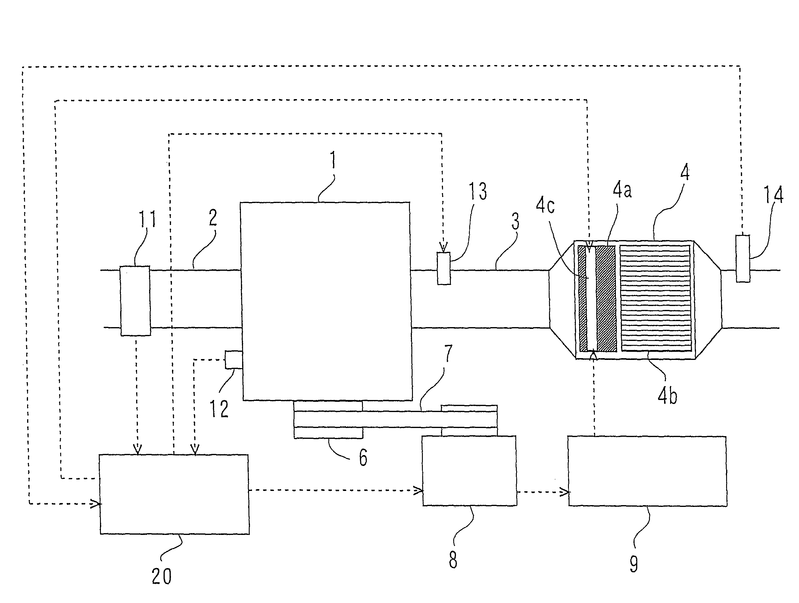
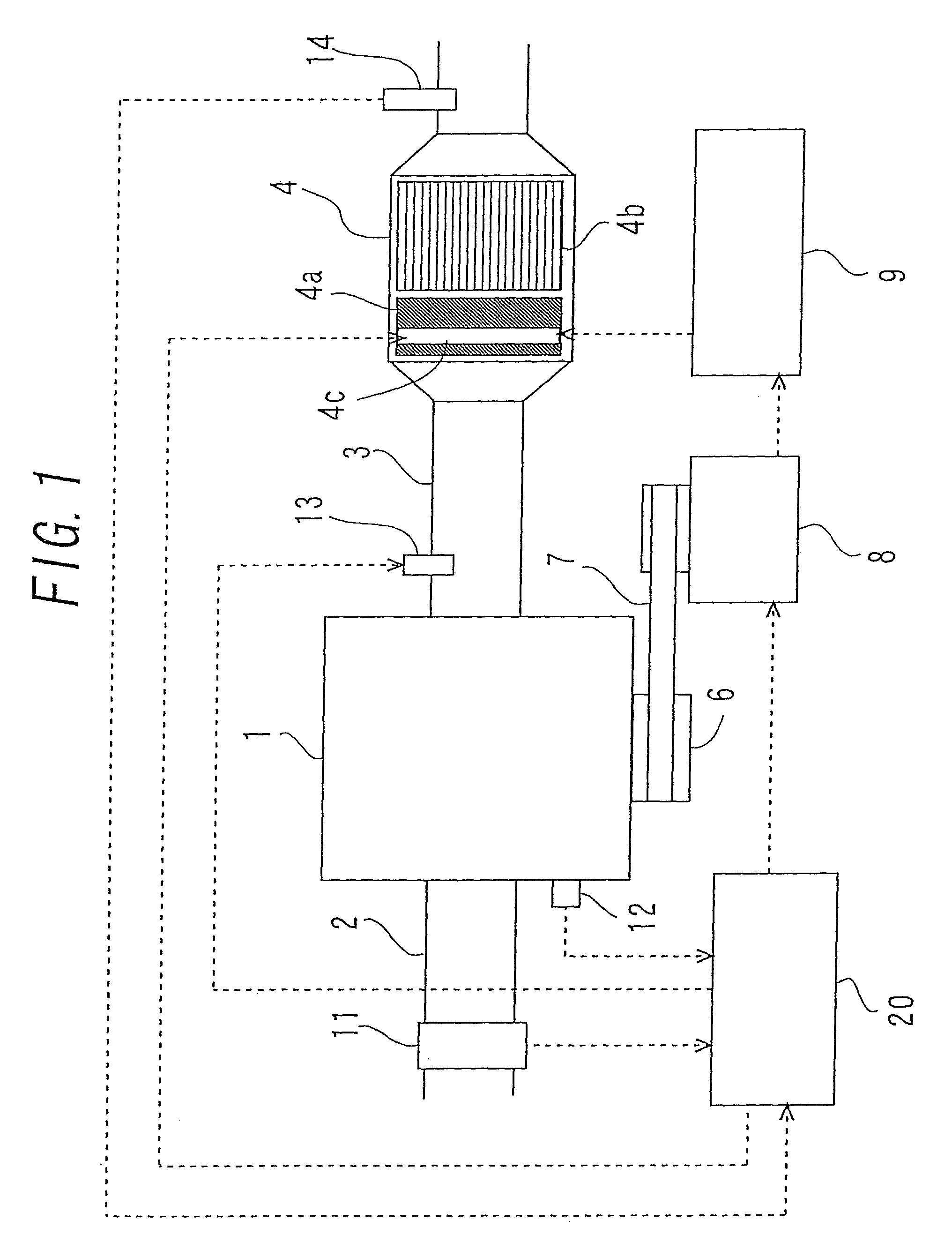
[0057]FIG. 1 illustrates a whole construction of an internal combustion engine, and intake / exhaust system and a control system, to which an embodiment 1 is applied. An intake pipe 2 and an exhaust pipe 3 are connected to an internal combustion engine 1, wherein fresh air is sucked via the intake pipe 2 into the internal combustion engine 1, and a post-combustion gas in the internal combustion engine 1 is discharged through the exhaust pipe 3. The intake pipe 2 is provided with an airflow meter 11 for detecting an intake air quantity.

[0058]The exhaust pipe 3 is provided with an exhaust gas purifying device 4 that purifies an exhaust gas. The exhaust gas purifying device 4 includes a DPNR 4b having a function of a filter that traps particulate matters in the exhaust gas and also a function of the occlusion-reduction type NOx catalyst that purifies the exhaust gas of NOx. Further, an EHC 4a capable of electrically raising a temperature is provided upstream of the DPNR 4b in the exhaust...

embodiment 2

[0092]An embodiment 2 of the present invention will be described. The constructions of the internal combustion engine, the intake / exhaust system and the control system in the embodiment 2 are the same as those described in the embodiment 1. Further, the embodiment 2 will discuss an example of how the charging level of the battery 9 is maintained by increasing the number of idling revolutions of the internal combustion engine 1 irrespective of the ON / OFF states of the electric heater 4c during the execution of the SOx poisoning recovery process of the DPNR 4b.

[0093]FIG. 4 shows a flowchart of the battery charging routine during the recovery of the SOx poisoning in the embodiment 2.

[0094]When executing the battery charging routine, at first, it is determined in S301 whether kept in the SOx poisoning recovery process or not. To be specific, this may be determined by detecting drive signals given to the electric heater 4c and to the fuel addition valve 13. If determined not to be kept ...

embodiment 3

[0099]Next, an embodiment 3 of the present invention will be described. The embodiment 3 will exemplify an example, wherein if the internal combustion engine stops during the SOx poisoning recovery process of the internal combustion engine, the electric heater is inhibited from being energized during a predetermined period when the internal combustion engine is started next time. The constructions of the internal combustion engine, the intake / exhaust system and the control system in the embodiment 3 are the same as those explained in the embodiment 1.

[0100]FIGS. 5 and 6 show a flowchart of an engine stop routine during the recovery of the SOx poisoning and a flowchart of a heater energizing inhibition routine at an engine startup time in the embodiment 3. To start with, the engine stop routine during the recovery of the SOx poisoning will be described.

[0101]Upon executing the engine stop routine, at first it is determined in S401 whether the operation is in the SOx poisoning recover...


PUM


Abstract

Provided is a technology enabling a temperature of an exhaust gas purifying device to rise more surely by operating an electric heater for a catalyst attached with the electric heater more steadily without exerting an excessive load on a battery. Included are the battery and the electric heater operating upon being supplied with electric power from the battery and heating an occlusion-reduction type NOx catalyst, wherein it is predicted, from a point that a SOx occluded quantity into the occlusion-reduction type NOx catalyst is equal to or larger than S1, that a SOx poisoning recovery process will be executed in near future (S102), and a charging level of the battery is increased (S106) by raising a voltage of power generation of an alternator (S103).

Description

CROSS REFERENCE TO RELATED APPLICATION[0001]This application is a National Stage of International Application No. PCT / JP2007 / 064290 filed Jul. 12, 2007, claiming priority based on Japanese Patent Application No. 2006-192147, filed Jul. 12, 2006, the contents of all of which are incorporated herein by reference in their entirety.TECHNICAL FIELD[0002]The present invention relates to a power source system of an internal combustion engine, which supplies electric power to and thus operates peripheral devices such as an electric heater of an exhaust gas purifying device.BACKGROUND ARTS[0003]An exhaust gas of an internal combustion engine contains toxic substances such as NOx. It is known that a NOx catalyst for purifying the exhaust gas of NOx is provided in an exhaust system of the internal combustion engine in order to reduce discharge of these toxic substances. This technology might cause a case in which when a temperature of the NOx catalyst is low, a NOx purifying efficiency decreas...

Claims


Application Information

Patent Timeline
Patent Type & Authority Patents(United States)
IPC IPC(8): F01N3/00F01N3/10
CPCF01N3/0871F01N3/2013F01N9/00F01N11/00F02D41/028F01N13/0097H02J7/1446F02D41/083F01N2550/22F02D2041/026F02D2200/503F02D2250/24Y02T10/26Y02T10/47Y02T10/12Y02T10/40
Inventor NIIMI, KUNIAKIODA, TOMIHISAUEDA, TAKANORITSUJIMOTO, KENICHI
Owner TOYOTA JIDOSHA KK
Why Eureka
Try Eureka