
Method and apparatus for providing a magnetic read sensor having a thin pinning layer and improved magnetoreistive coefficient

a magnetic read and magnetoreistive coefficient technology, applied in nanoinformatics, instruments, transportation and packaging, etc., can solve the problems of degrading the performance of the read head and weak exchange coupling field, and achieve the effect of high positive magnetostriction

Inactive Publication Date: 2011-01-18
WESTERN DIGITAL TECH INC
View PDF32 Cites 6 Cited by
  • Summary
  • Abstract
  • Description
  • Claims
  • Application Information

AI Technical Summary

Benefits of technology

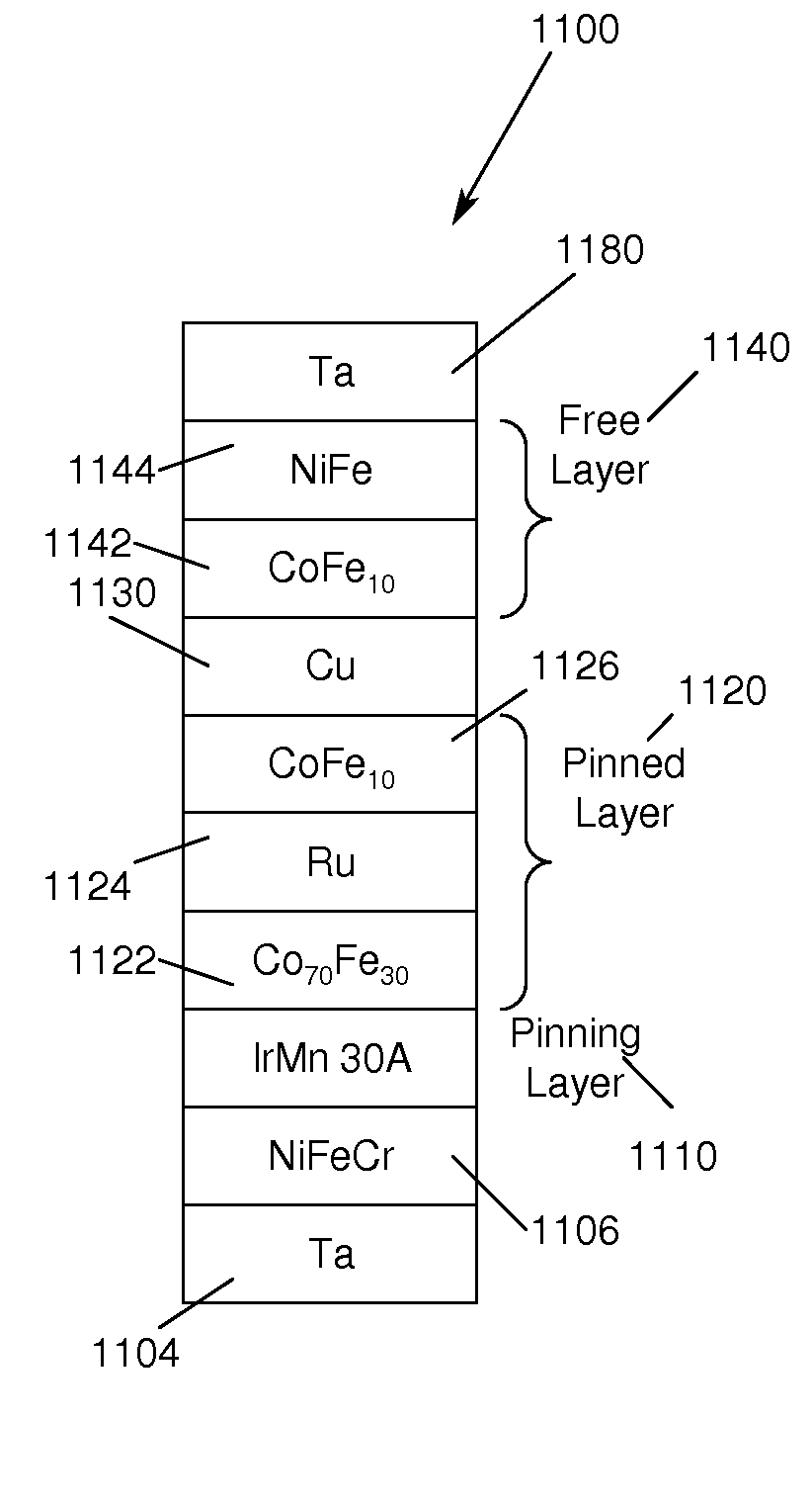
[0017]A magnetic read head in accordance with the principles of the present invention includes a ferromagnetic pinned layer structure comprising at least two pinned layers, the ferromagnetic pinned structure having a high positive magnetostriction, a iridium manganese (IrMn) alloy pinning layer, exchange coupled to the pinned layer structure, for pinning the magnetic moment of the pinned layer structure, a free layer structure having a first magnetization that is free to rotate and a spacer layer disposed between the free layer structure and the ferromagnetic pinned layer structure, wherein the at least two pinned layers of the ferromagnetic pinned layer structure provide maximum exchange coupling between the pinned layer structure and the iridium manganese alloy pinning layer and wherein thickness of at least two of the pinned layers are equal.
[0019]In another embodiment of the present invention, a method for providing a magnetic read sensor having a thin pinning layer and improved magnetoresistive coefficient is provided. The method includes forming a ferromagnetic pinned layer structure comprising at least two pinned layers, the ferromagnetic pinned structure having a high positive magnetostriction, forming a iridium manganese (IrMn) alloy pinning layer, exchange coupled to the pinned layer structure, for pinning the magnetic moment of the pinned layer structure, forming a free layer structure having a first magnetization that is free to rotate and forming a spacer layer disposed between the free layer structure and the ferromagnetic pinned layer structure, wherein the at least two pinned layers of the ferromagnetic pinned layer structure provide maximum exchange coupling between the pinned layer structure and the iridium manganese alloy pinning layer and wherein thickness of at least two of the pinned layers are equal.

Problems solved by technology

If the coercivity of the pinned layer exceeds the exchange coupling field between the pinning and pinned layers the exchange coupling field will not be strong enough to bring the magnetic moment of the pinned layer back to the original pinned direction.
If the pinning field Hp is low, the orientation of the pinned layer will not be controlled thereby degrading performance of the read head.

Method used


Image

  • Method and apparatus for providing a magnetic read sensor having a thin pinning layer and improved magnetoreistive coefficient
  • Method and apparatus for providing a magnetic read sensor having a thin pinning layer and improved magnetoreistive coefficient
  • Method and apparatus for providing a magnetic read sensor having a thin pinning layer and improved magnetoreistive coefficient

Examples


Embodiment Construction

[0038]In the following description of the embodiments, reference is made to the accompanying drawings that form a part hereof, and in which is shown by way of illustration the specific embodiments in which the invention may be practiced. It is to be understood that other embodiments may be utilized because structural changes may be made without departing from the scope of the present invention.

[0039]The present invention provides a method and apparatus for providing a magnetic read sensor having a thin pinning layer and improved magnetoresistive coefficient ΔR / R.

[0040]The present invention provides a thin IrMn alloy pinning layer adjacent a composite pinned layer, wherein the percentage of iron in the pinned layer adjacent the thin IrMn alloy pinning layer in the range of 20-40% to provide maximum pinning. It also may be desirable for the thicknesses of the outer ferromagnetic layers to be comparable.

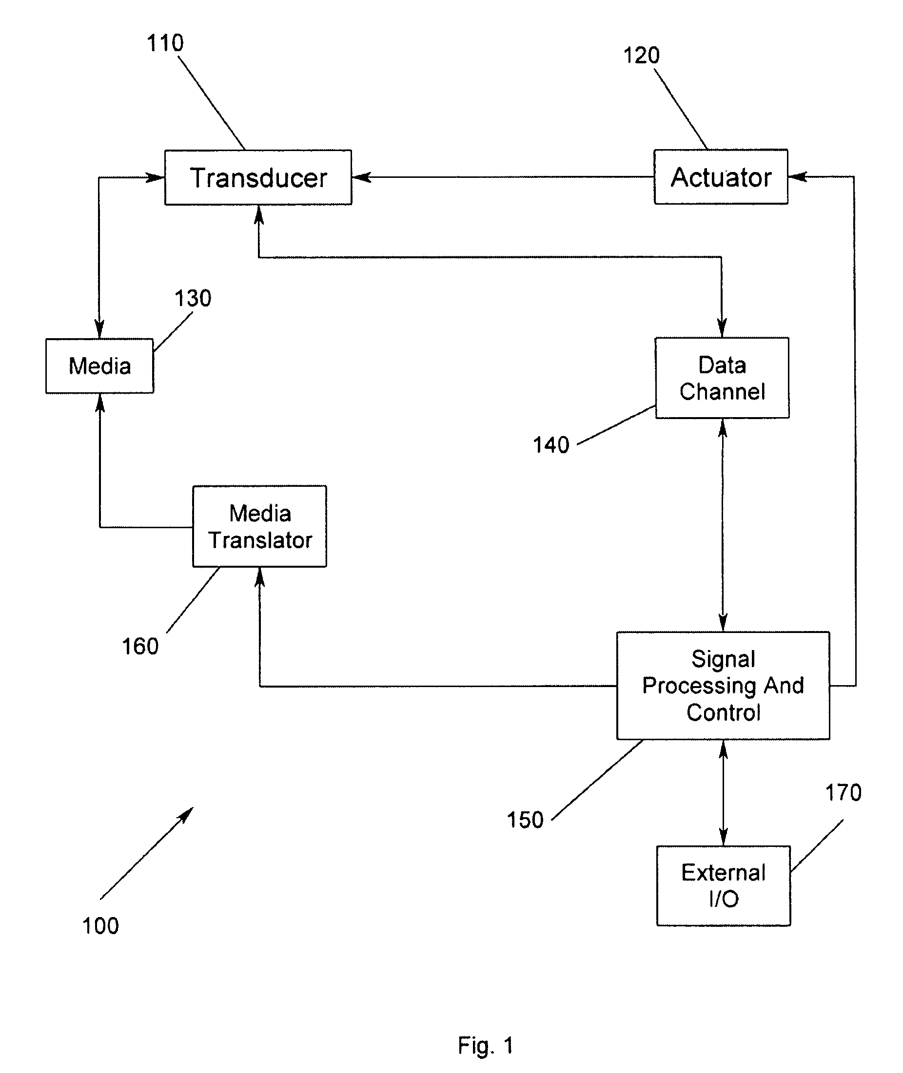
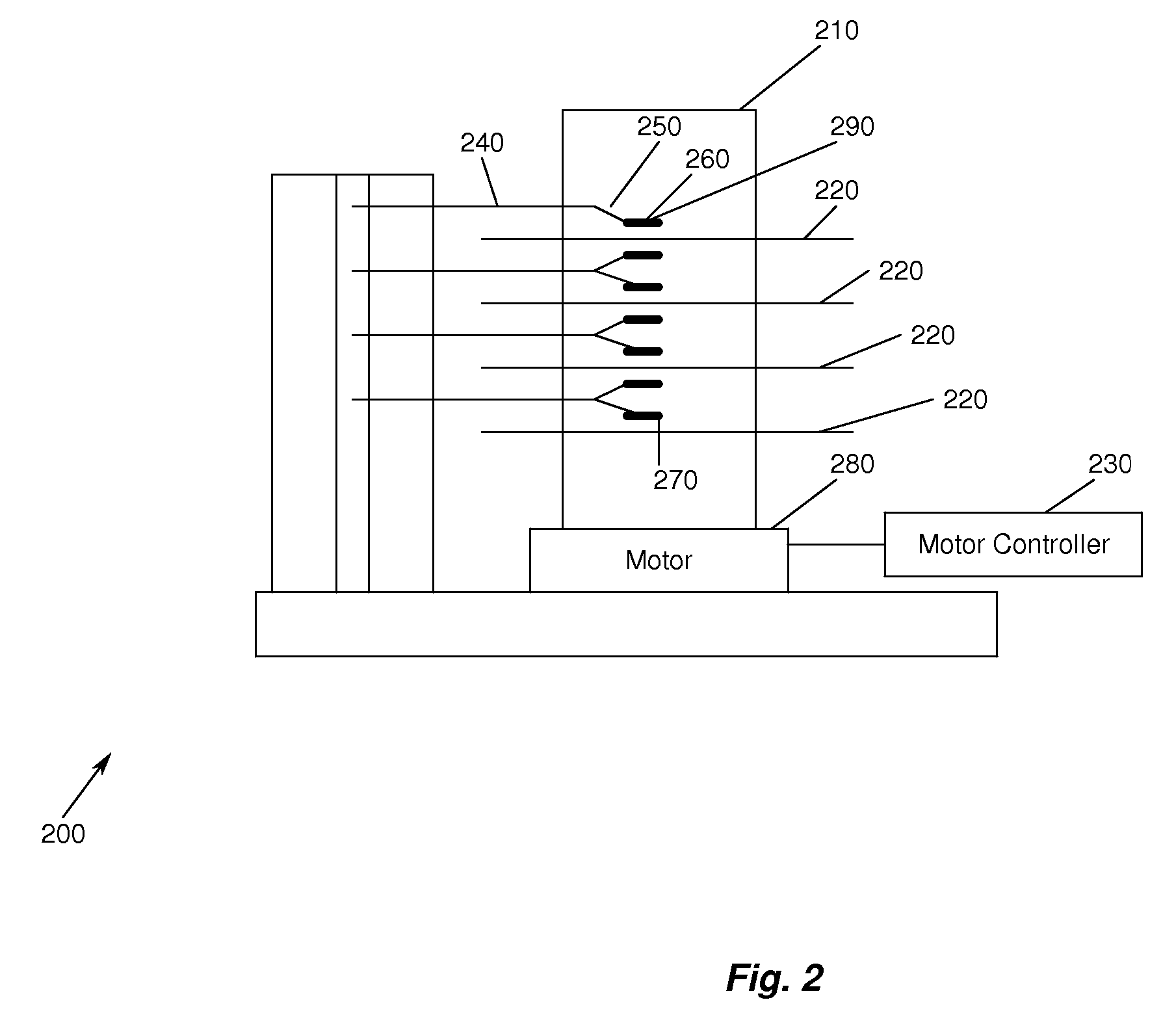
[0041]FIG. 1 illustrates an exemplary storage system 100 according to the present i...


PUM

PropertyMeasurementUnit
magnetostrictionaaaaaaaaaa
magnetic momentaaaaaaaaaa
magnetizationaaaaaaaaaa

Abstract

A method and apparatus for providing a magnetic read sensor having a thin pinning layer and improved magnetoresistive coefficient ΔR / R is disclosed. A thin IrMn alloy pinning layer is disposed adjacent a composite pinned layer, wherein the percentage of iron in the pinned layer adjacent the thin IrMn alloy pinning layer in the range of 20-40% to provide maximum pinning.

Description

RELATED APPLICATION[0001]This application is a continuation-in-part of U.S. application Ser. No. 10 / 837,280, filed Apr. 30, 2004, which is hereby incorporated by reference.BACKGROUND OF THE INVENTION[0002]1. Field of the Invention[0003]This invention relates in general to magnetic read sensors, and more particularly to a method and apparatus for providing a magnetic read sensor having a thin pinning layer and improved magnetoresistive coefficient ΔR / R.[0004]2. Description of Related Art[0005]The heart of a computer is typically a magnetic disk drive which includes a rotating magnetic disk, a slider that has write and read heads, a suspension arm above the rotating disk and an actuator arm. The suspension arm biases the slider into contact with a parking ramp or the surface of the disk when the disk is not rotating but, when the disk rotates, air is swirled by the rotating disk adjacent an air bearing surface (ABS) of the slider causing the slider to ride on an air bearing a slight d...

Claims


Application Information

Patent Timeline
Patent Type & Authority Patents(United States)
IPC IPC(8): G11B5/39G11B5/127G11B5/33
CPCB82Y10/00B82Y25/00G11B5/3932Y10T428/1121G11B2005/3996G11B5/3906G01R33/093G01R33/098H10N50/85H10N50/01H10N50/10G11C11/00C23C14/00G01R33/09
Inventor GILL, HARDAYAL SINGH
Owner WESTERN DIGITAL TECH INC
Learn More