System executing log data transfer synchronously and database data transfer asynchronously

a log data and database technology, applied in the field of system executing log data transfer synchronously and database data transfer asynchronously, can solve the problems of deteriorating performance of active database management system and vanishing of latest transactions on the main site, so as to prevent deterioration in performance of active database management system and avoid transaction misses

Inactive Publication Date: 2011-02-15
HITACHI LTD
View PDF69 Cites 178 Cited by
  • Summary
  • Abstract
  • Description
  • Claims
  • Application Information

AI Technical Summary

Benefits of technology

[0019]An object of the present invention is to provide a system in which missing of transactions is avoided while deterioration in performance of an active database management system is prevented.

Problems solved by technology

In the conventional method for executing log data transfer synchronously and DB data transfer synchronously, the performance of the active database management system is apt to deteriorate because increase in distance between the main site and the recovery site or increase in delay on the link has a direct bearing on increase in response time of the write processes issued from the active database management system to both the log logical disk and the DB data logical disk of the main storage system.
On the other hand, in the conventional method for executing log data transfer asynchronously and DB data transfer asynchronously, there is a possibility that some of the latest transactions committed on the main site may vanish at the time of restart of the standby database management system because there is a possibility that information of all transactions committed by the active database management system may not be reflected on the sub storage system.

Method used


Image

  • System executing log data transfer synchronously and database data transfer asynchronously
  • System executing log data transfer synchronously and database data transfer asynchronously
  • System executing log data transfer synchronously and database data transfer asynchronously

Examples


Embodiment Construction

[0036]A system according to an embodiment of the invention will be described below. Incidentally, it is a matter of course that the invention is not limited to the following embodiment.

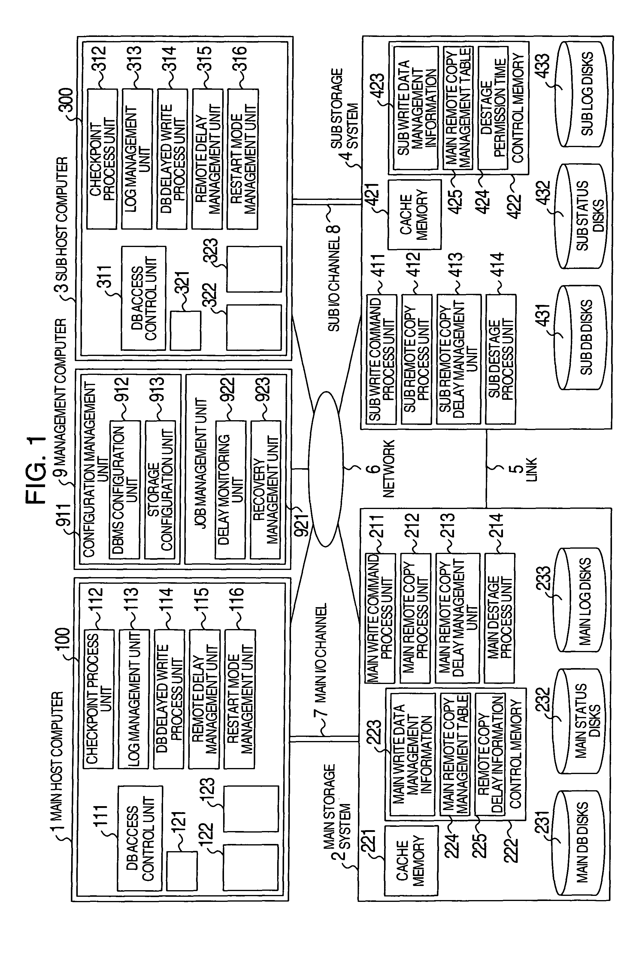
[0037]FIG. 1 is a diagram showing the configuration of the system according to this embodiment. The system according to this embodiment has a main host computer 1, a main storage system 2, a sub host computer 3, a sub storage system 4, and a management computer 9. The constituent members of the system are connected to one another through a network 6. The main storage system 2 and the sub storage system 4 are connected to each other through a link 5.

[0038]An active database management system 100 of the main host computer 1 (which may be achieved by a computer or information processor or may be achieved by a program or object that can execute the processing) includes a DB access control unit 111, a checkpoint process unit 112, a log management unit 113, a DB delayed write process unit 114, and a remote ...


PUM


Abstract

A disaster recovery system and a method therefor, having: a function for receiving write requests from a host computer to write log information indicating the contents of a database process executed for a database buffer on a main site, database data updated on the database buffer and status information indicating the position of log information used for disaster recovery; a function for transferring the received write request for log information to a recovery site by a synchronous remote copy process; and a function for transferring the received write request for database data to the recovery site by an asynchronous remote copy process. While remote copy can be executed at a long distance without data loss, the deterioration of the performance of a database process on a main site can be suppressed.

Description

BACKGROUND OF THE INVENTION[0001]The present invention relates to a technique for committing processing executed by a certain information processing system to another information processing system or a program or object for executing the processing at the time of occurrence of a disaster or predetermined condition in the certain information processing system or in accordance with a request. Particularly it relates to a database management system.[0002]In a conventional database management system, a storage region (hereinafter referred to as “DB buffer”) is reserved on a memory of a computer (hereinafter referred to as “database server” or “DB server”) executing a database management program so that update data (hereinafter referred to as “DB data”) are temporarily stored in the DB buffer to increase the speed of rewriting of the DB data (table space) into a database by a transaction. The data written on the DB buffer are finally written in a storage system having a nonvolatile stora...

Claims


Application Information

Patent Timeline
Patent Type & Authority Patents(United States)
IPC IPC(8): G06F7/00G06F17/00G06F3/06G06F11/14G06F11/20G06F12/00G06F17/30
CPCG06F11/1471G06F11/2064G06F11/2074G06F11/2038G06F11/2048G06F2201/80
Inventor OEDA, TAKASHIKAWAMURA, NOBUOYAMAGUCHI, KOTA
Owner HITACHI LTD
Why Eureka
Try Eureka