
Flow restricted seat ring for pressure regulators

Active Publication Date: 2011-03-01
FISHER CONTROLS INT LLC
View PDF14 Cites 15 Cited by
  • Summary
  • Abstract
  • Description
  • Claims
  • Application Information

AI Technical Summary

Benefits of technology

The present disclosure is about a seat that is designed to control the flow of fluid in a control device. The seat has a sealing surface that is in contact with a sealing disk to prevent fluid from directly impacting the control member. The seat also has one or more orifices that are positioned in the flow-path to direct the fluid flow. The seat can be designed with a cylindrical inner surface or a frustoconical inner surface to achieve the desired fluid flow control. The technical effect of this design is to provide precise control over fluid flow in a control device, which can improve the overall performance and efficiency of the device.

Problems solved by technology

Upon impact, the debris or particulate matter can damage the rubber and thereby effect the performance of the regulator.

Method used


Image

  • Flow restricted seat ring for pressure regulators
  • Flow restricted seat ring for pressure regulators
  • Flow restricted seat ring for pressure regulators

Examples


Embodiment Construction

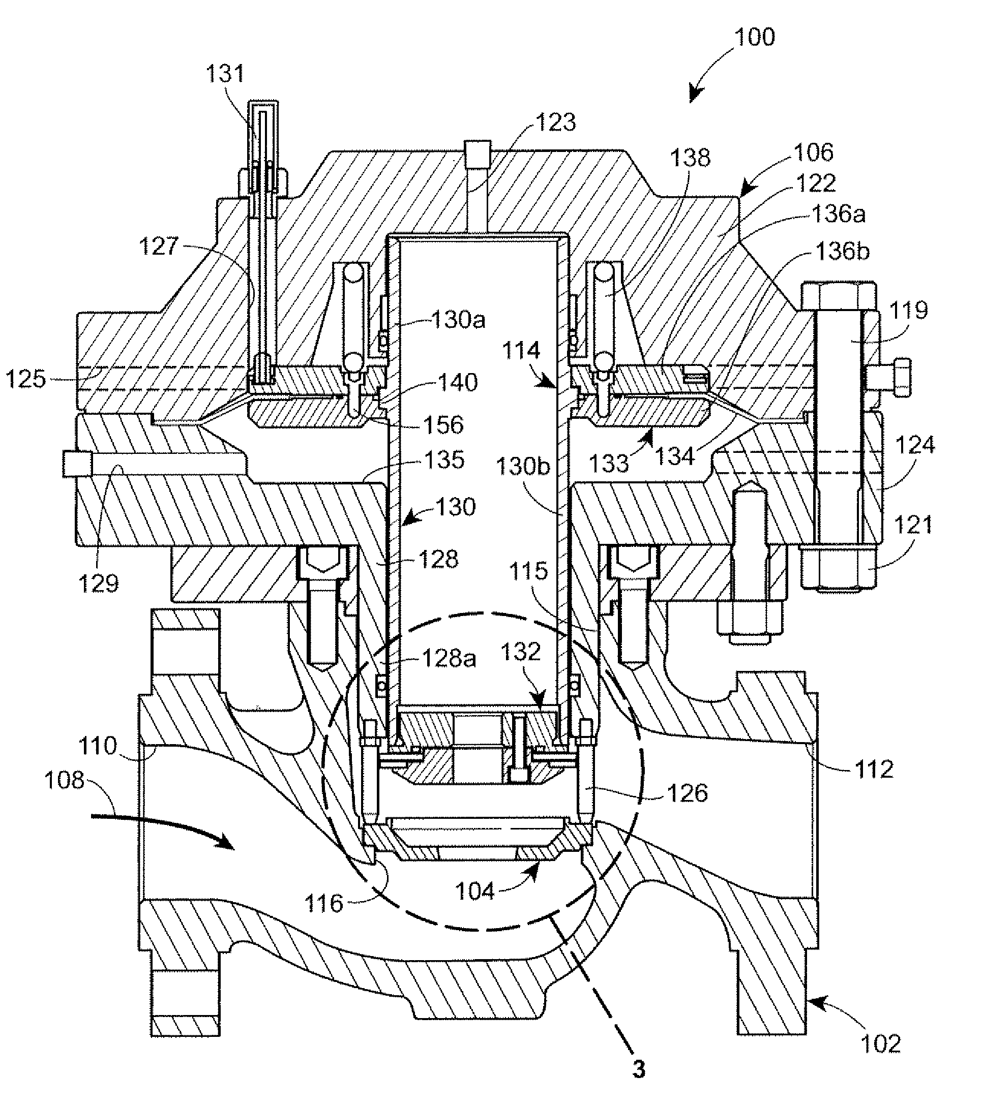
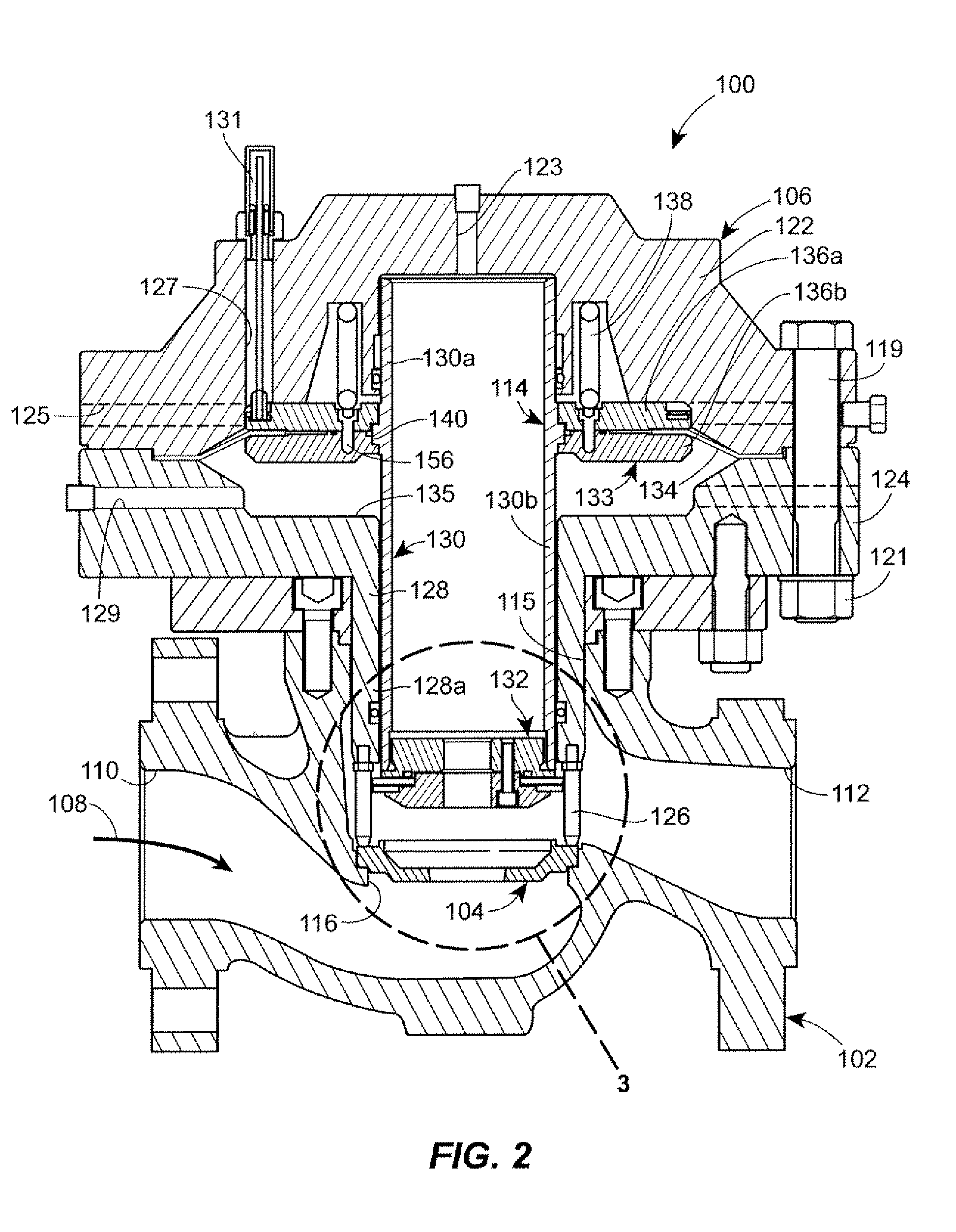
[0018]Referring to FIGS. 2-4, a control device in accordance with the principles of the present disclosure includes a pressure regulator 100. The pressure regulator 100 generally includes a valve body 102, a seat ring 104, and an actuator 106. The valve body 102 defines a flow-path 108 extending between an inlet 110 and an outlet 112. The actuator 106 includes a control assembly 114 that is moveable between an open position, as is shown in FIG. 1, and a closed position, wherein the control assembly 114 engages the seat ring 104. Movement of the control assembly 114 occurs in response to fluctuations in the pressure of the fluid traveling through the flow-path 108. Accordingly, the position of the control assembly 114 relative to the seat ring 104 effects a flow capacity of the pressure regulator 100.

[0019]Referring specifically to FIGS. 2 and 3, the valve body 102 further defines a throat 116 between the inlet 110 and the outlet 112. The throat 116 includes a stepped portion 118 acc...


PUM


Abstract

A control device includes a valve body, a seat ring, and an actuator. The valve body defines a flow-path for a fluid. The seat ring is disposed within the flow-path. The actuator is coupled to the valve body and includes a control member. The control member is adapted for displacement relative to the seat ring for regulating a flow of the fluid through the flow-path. The control member includes a scaling disk adapted to sealingly engage the seat ring and close the flow-path. The seat ring includes an orifice disposed within the flow-path such that the seat ring prevents at least a portion of the flow of the fluid from substantially perpendicularly impacting the sealing disk.

Description

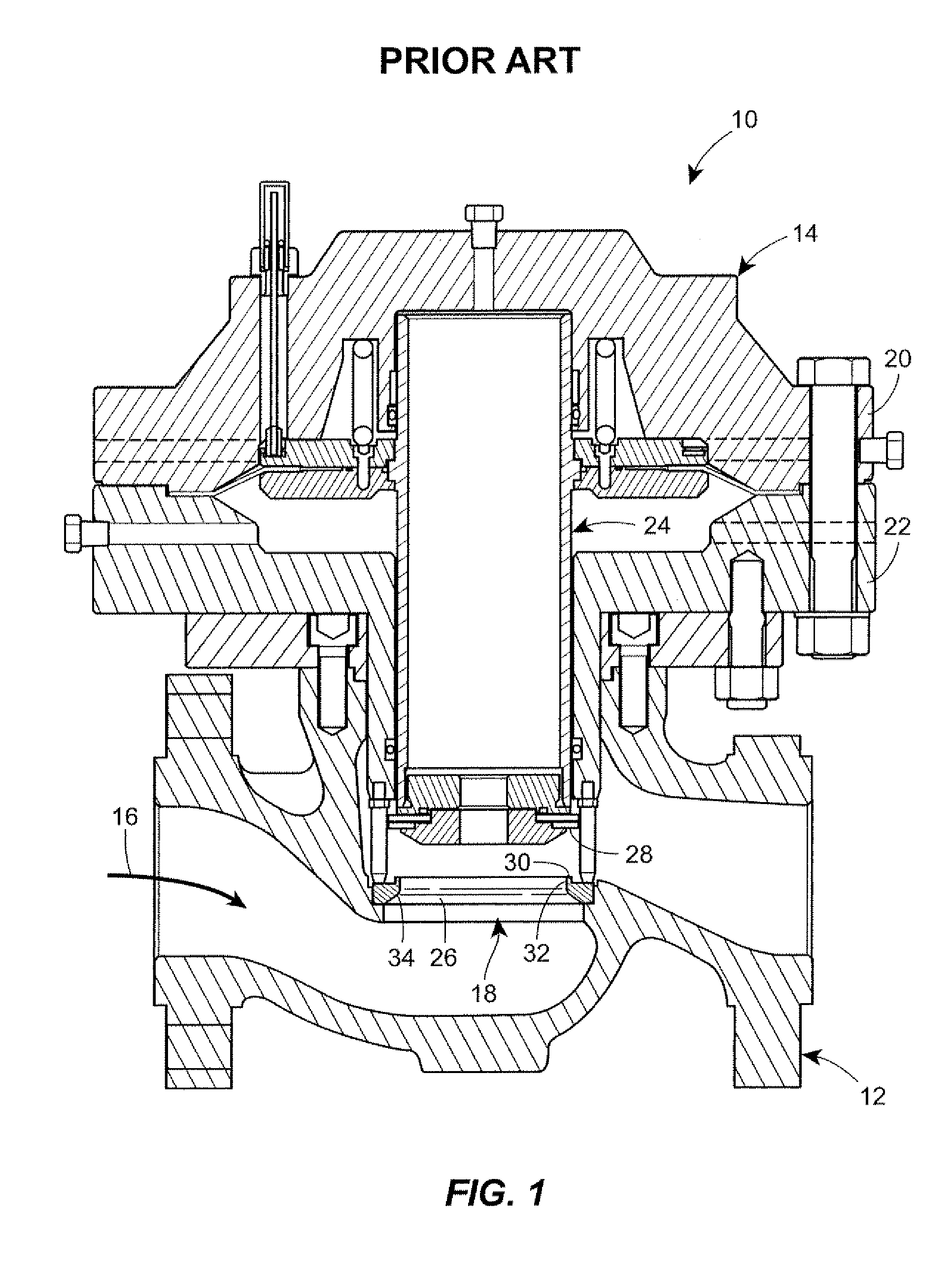
FIELD OF THE DISCLOSURE[0001]The present disclosure generally relates to fluid control devices and, more particularly, to seat rings for fluid control devices.BACKGROUND[0002]Fluid control devices include various categories of equipment including control valves and regulators. Such control devices are adapted to be coupled within a fluid process control system such as chemical treatment systems, natural gas delivery systems, etc., for controlling the flow of a fluid therethrough. Each control device defines a fluid flow-path and includes a control member for adjusting a dimension of the flow-path. For example, FIG. 1 depicts a known regulator assembly 10 including a valve body 12 and an actuator 14. The valve body 12 defines a flow-path 16 and includes a throat 18. In FIG. 1, the regulator assembly 10 is configured in a flow-up configuration. The actuator 14 includes an upper actuator casing 20, a lower actuator casing 22, and a control member 24. The control member 24 is disposed w...

Claims


Application Information

Patent Timeline
Patent Type & Authority Patents(United States)
IPC IPC(8): F16K1/34
CPCF16K31/1262F16K47/14F16K1/427Y10T137/86759
Inventor WEYER, JR., THOMAS L.ROPER, DANIEL G.GRIFFIN, JR., JAMES L.MCKINNEY, HAROLD J.SCHEFFLER, DOUGLAS J.
Owner FISHER CONTROLS INT LLC
Learn More