Cryosurgical probe with vacuum insulation tube assembly

a vacuum insulation tube and probe technology, applied in the field of cryosurgical probes, can solve the problem of relatively expensive brazing and other problems

Inactive Publication Date: 2011-03-22
ENDOCARE
View PDF14 Cites 22 Cited by
  • Summary
  • Abstract
  • Description
  • Claims
  • Application Information

AI Technical Summary

Problems solved by technology

Brazing is a relatively expensive endeavor.

Method used


Image

  • Cryosurgical probe with vacuum insulation tube assembly
  • Cryosurgical probe with vacuum insulation tube assembly
  • Cryosurgical probe with vacuum insulation tube assembly

Examples


Embodiment Construction

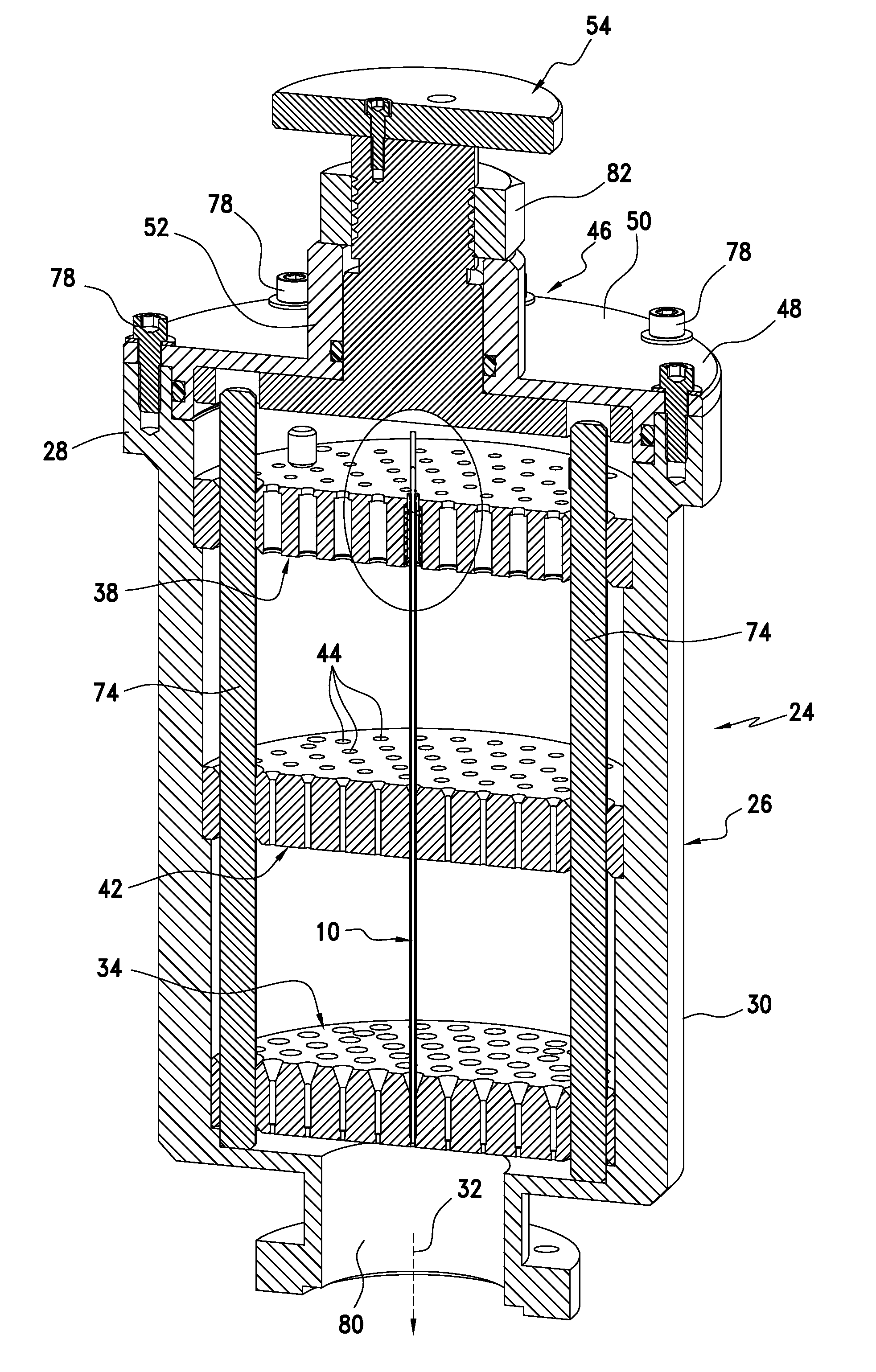
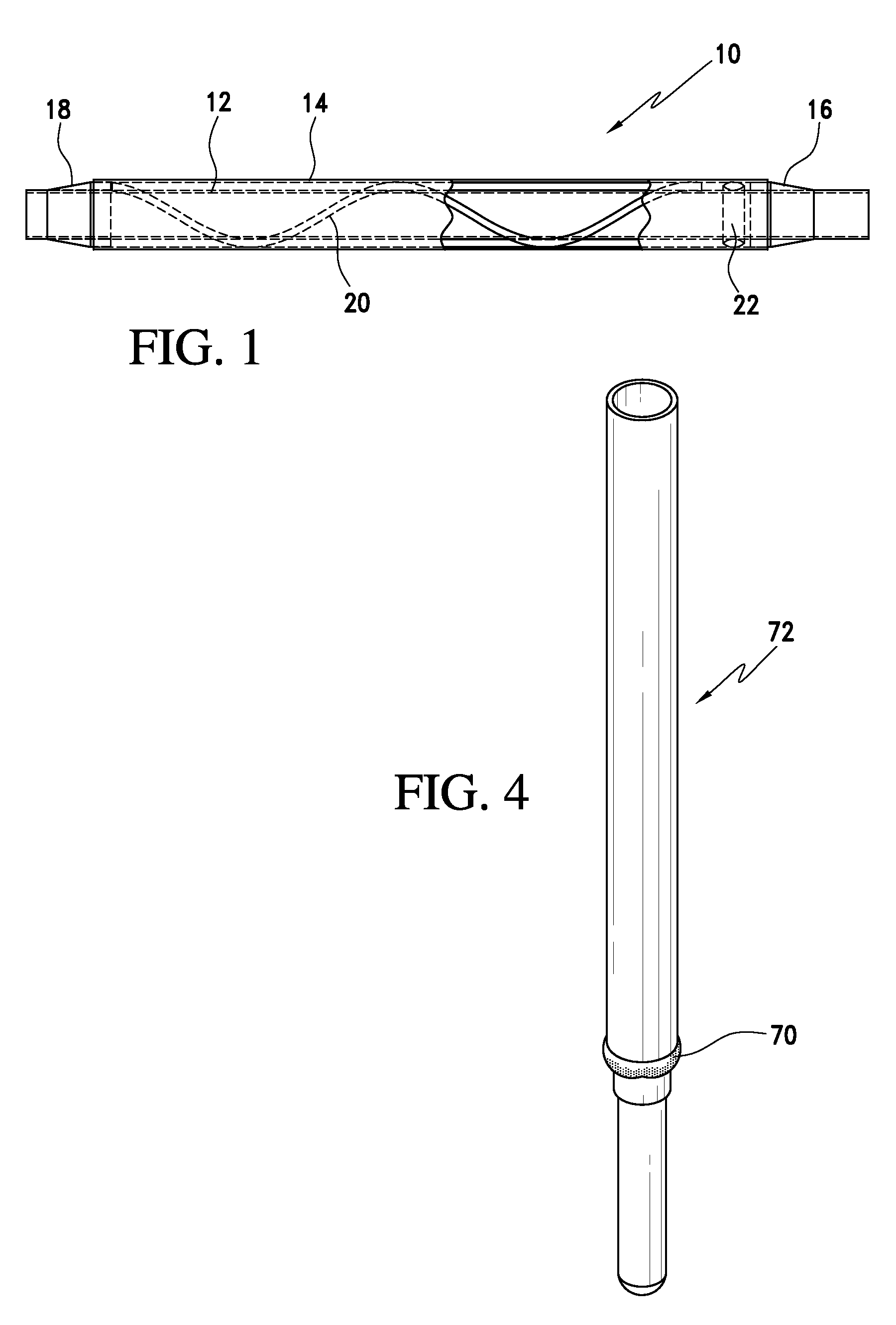
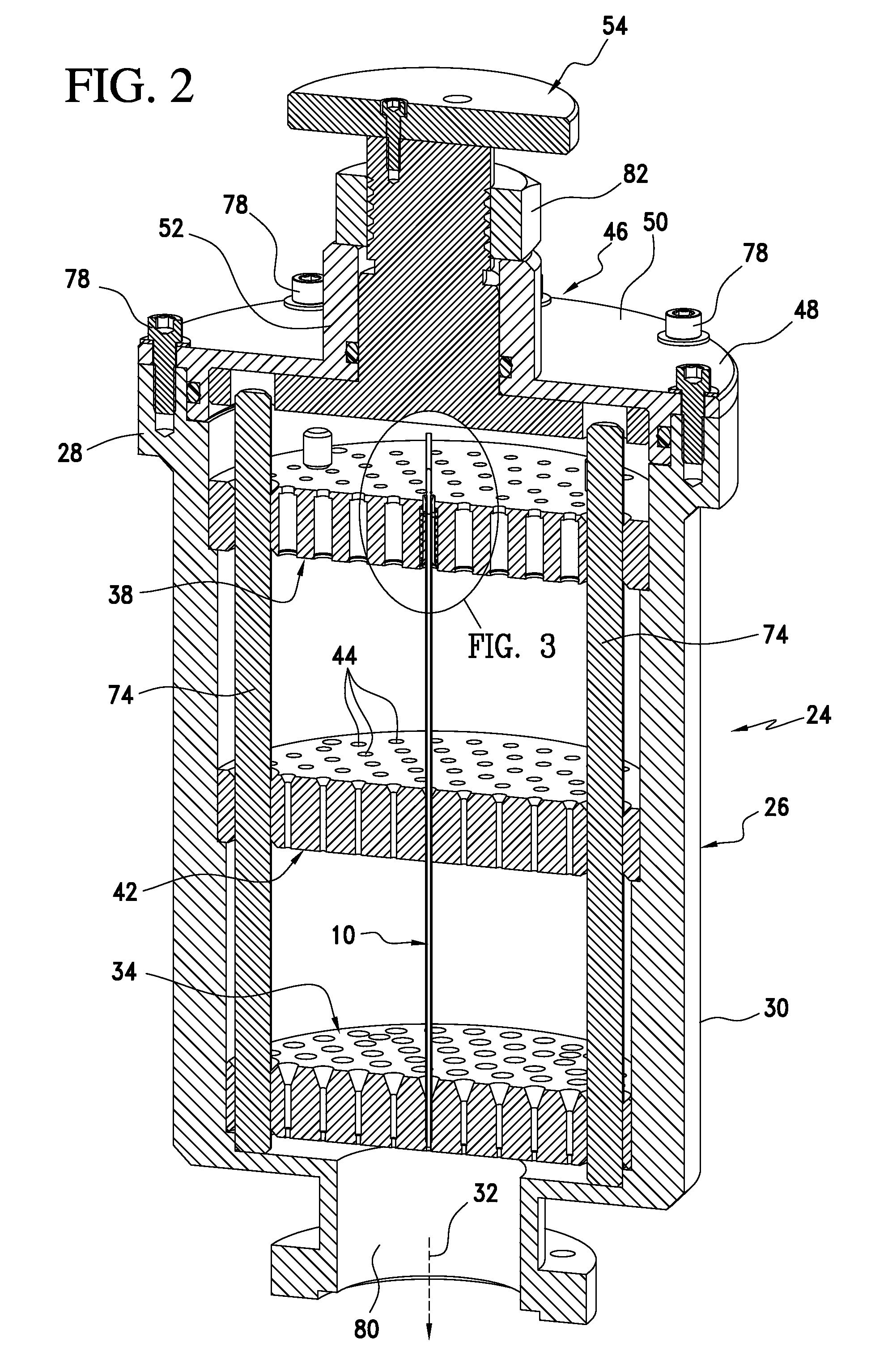
[0018]Referring now to the drawings and the characters of reference marked thereon, FIG. 1 illustrates a preferred embodiment of the vacuum insulation tube assembly of the present invention, designated generally as 10. The vacuum insulation tube assembly 10 is utilized as a component in a cryosurgical probe, as will be described below in more detail. It includes an inner tube 12; and, an outer tube 14 concentrically positioned about the inner tube 12. The outer tube 14 is securely soldered at end portions 16, 18 of the inner tube 12 to form a vacuum space between the inner tube 12 and the outer tube 14. The tubes are preferably formed of stainless steel or titanium alloy. The vacuum insulation tube assembly 10 includes a thermally insulative spacing element 20 positioned between the inner tube 12 and the outer tube 14. The spacing element is helically twisted about the inner tube 12. It is preferably formed of a ceramic material such as ceramic fiber. The vacuum insulation tube asse...


PUM

PropertyMeasurementUnit
interior volumeaaaaaaaaaa
pressureaaaaaaaaaa
vacuumaaaaaaaaaa

Abstract

A vacuum insulation tube assembly which is utilized as a component in a cryosurgical probe. The vacuum insulation tube assembly includes an inner tube; and, an outer tube concentrically positioned about the inner tube. The outer tube is securely soldered at end portions of the inner tube and forms a vacuum space between the inner tube and the outer tube. The vacuum tube assemblies may be conveniently mass produced using a special fixture.

Description

BACKGROUND OF THE INVENTION[0001]1. Field of the Invention[0002]The present invention relates to cryosurgical probes and more particularly to a cryosurgical probe with an improved vacuum insulation tube assembly and method of manufacture thereof which facilitates economical mass production of precision cryosurgical probes.[0003]2. Description of the Related Art[0004]Cryosurgery involving the use of a cryosurgical probe assemblies typically involves the use of cryoprobes that are each attached to a handle that are, in turn, connected to a high-pressure fluid line with a quick-disconnect for attachment to a fluid source.[0005]Cryosurgical probes manufactured by present assignee Endocare, Inc., Irvine, Calif., utilize a vacuum insulation tube that provides selected non-cooling areas on the surface of the cryoprobe. For example, U.S. Pat. Publication US 20050192565 (U.S. patent Ser. No. 11 / 116,873), to Eum et al, entitled “Detachable Cryosurgical Probe With Breakaway Handle”, incorporat...

Claims


Application Information

Patent Timeline
Patent Type & Authority Patents(United States)
IPC IPC(8): B23K37/04
CPCA61B18/02F16L9/18F16L59/065F16L59/14A61B2018/0262
Inventor DUONG, THACHLIU, JENNY C.EUM, JAY J.
Owner ENDOCARE
Why Eureka
Try Eureka