Method and apparatus for prosthetic limb rotation control

a technology of rotation control and prosthetic limbs, applied in the field of motorized prosthetic limbs, can solve the problems of slow rotational control of the arm, unnatural, impede the prosthetic control,

Active Publication Date: 2011-04-12
REHABILITATION INST OF CHICAGO
View PDF5 Cites 57 Cited by
  • Summary
  • Abstract
  • Description
  • Claims
  • Application Information

AI Technical Summary

Benefits of technology

[0013]Finally, the prosthetic limb may be provided with a shield cap made from a high magnetic permeability material in order to avoid interference from

Problems solved by technology

As a result, the rotational control of the arm is slow, unnatural, and cannot maintain inherent proprioceptive awareness of limb rotation.
This lack of proprioceptive feedback impedes prosthetic control, increases the cognitive burden of using a prosthesis and impairs functions in all applications.
Existing upper limb prosthetic rotators have not been adapted for rotation of lower limb prostheses because lower limb prostheses are all passively controlled; there is currently no analog in the lower limb to body-powered or myoelectric control in the upper limb.
Ther

Method used


Image

  • Method and apparatus for prosthetic limb rotation control
  • Method and apparatus for prosthetic limb rotation control
  • Method and apparatus for prosthetic limb rotation control

Examples


examples

[0043]The following examples further illustrate the invention but, of course, should not be construed as in any way limiting its scope.

example i

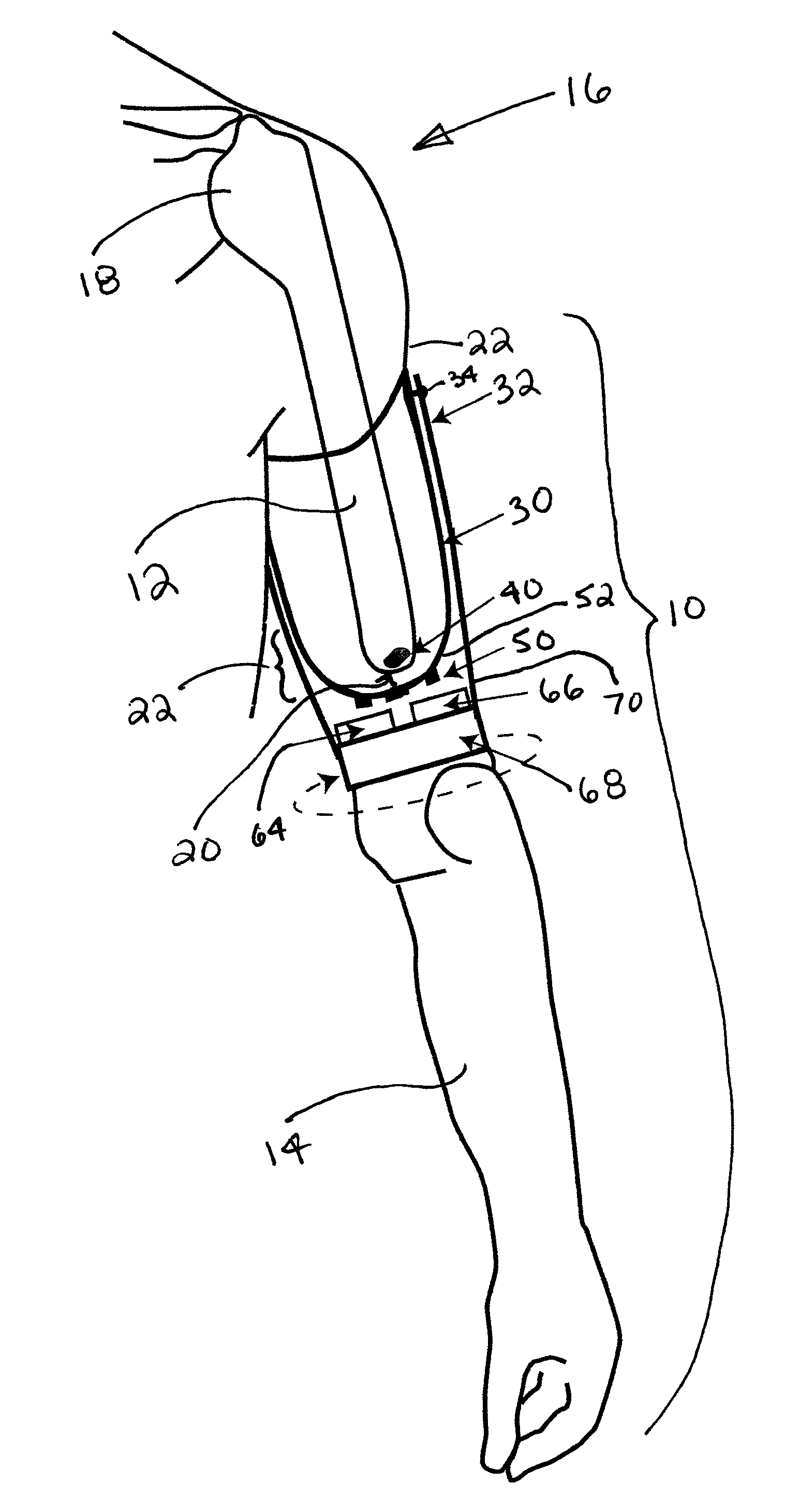
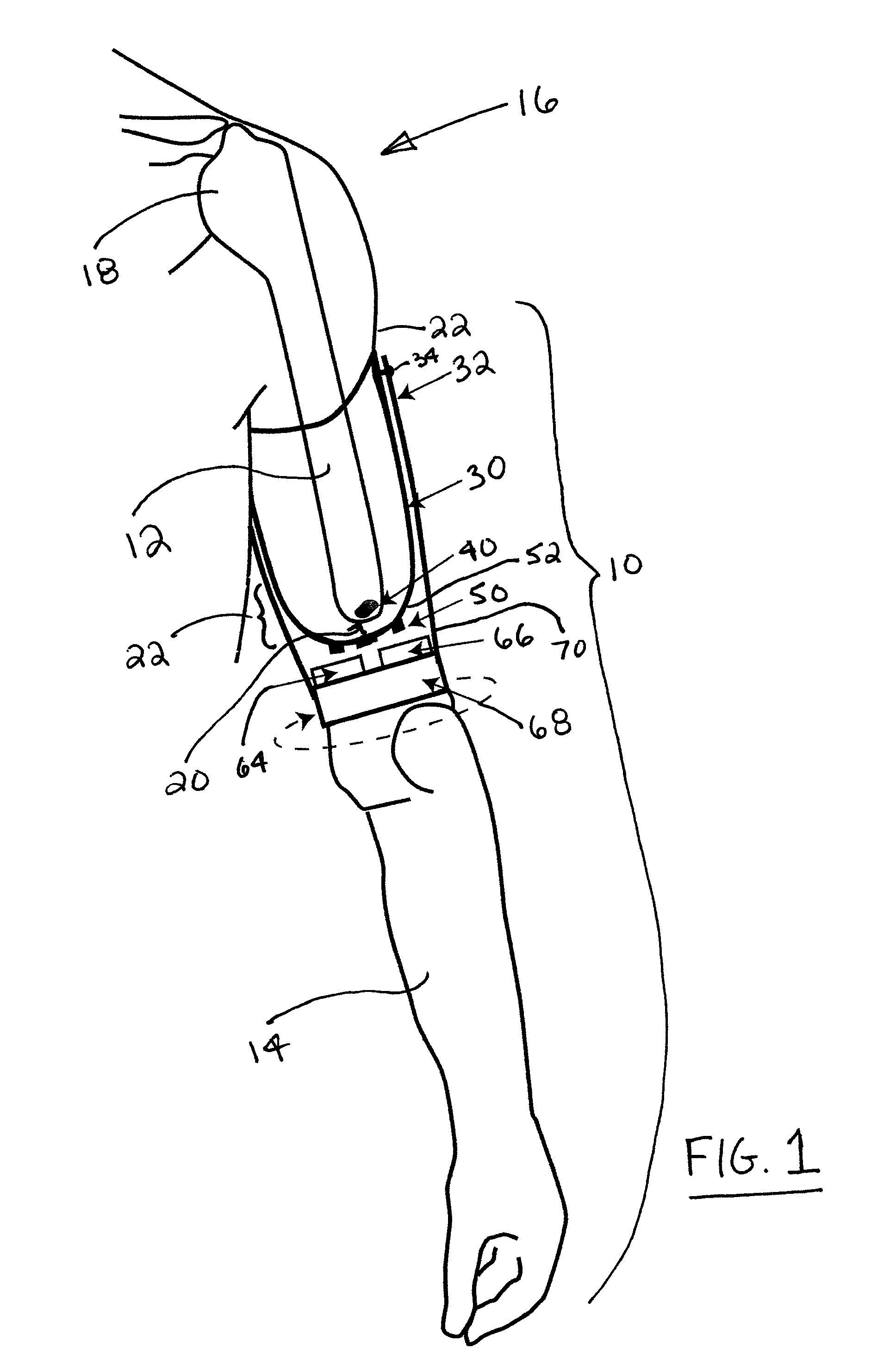
[0044]A simulation study as described below was conducted with finite element models of the upper arm to demonstrate details of the approach of the invention in sensing the rotation of a residual humerus. Further details of the study and related implementation of the invention are described in Li G, Kuiken T. A. “Modeling of Prosthetic Limb Rotation Control by Sensing Rotation of Residual Arm Bone,”IEEE Trans Biomed Eng., 55(9): 2134-2142, September 2008.

[0045]While the invention also can be used for controlling pronation and supination of the forearm in a below-elbow amputee, the upper arm was chosen in the study due to its greater symmetry allowing a simpler model, and because the upper arm is larger in size than the forearm, which would attenuate the magnetic fields so that a sensitivity analysis is more relevant. This analysis included the effects of arm size, magnet dimensions, relative position of the magnet to magnetic sensors, orientation of the magnet relative to the limb a...

example ii

[0052]Based on the modeling and simulation performed in Example 1, a further study was carried out to implement working physical models of the system for both transradial and transhumeral amputees. The number of sensors required to uniquely determine the location and orientation of the magnet in the distal end of the residual humerus was examined, and various algorithms for tracking a magnet's translation and orientation in space were evaluated using computer simulations. The algorithm with the best performance was then implemented on working physical models of the system. The physical models were used to determine the overall error in the system caused by translations of the magnet in three dimensions, offsets in the position of the magnet within the residual bone, and interference from external magnetic fields.

Methods

A. System Characterization

[0053]For both applications—transradial and transhumeral—the X-axis was taken as along the length of the limb, with positive sense facing di...


PUM


Abstract

A method and apparatus for improving the control of prosthetic limb rotation in amputees in which a permanent magnet is implanted into the distal end of a residual bone and the bone rotation is sensed from movement of the magnetic field of the magnet and used to effect corresponding rotation of the prosthetic limb.

Description

CROSS-REFERENCE TO RELATED PATENT APPLICATIONS[0001]This patent application claims the benefit of U.S. Provisional Patent Application No. 61 / 053,865, filed May 16, 2008.FIELD OF THE INVENTION[0002]This invention pertains generally to motorized prostheses and, more particularly, to a motorized prosthetic limb for attachment to a residual bone to instantaneously convert residual bone rotation into prosthetic limb rotation.BACKGROUND OF THE INVENTION[0003]Limb rotation is valuable—if not essential—for performing daily tasks. For example, forearm and humeral rotations are important motions employed in virtually all activities of daily living and are essential motions for controlling upper limb prostheses. Femoral rotation is not typically provided for lower limb prostheses, but if available, would allow lower limb amputees to more easily perform activities such as dressing or transferring in and out of vehicles. Currently, passive devices constitute the majority of commercially availabl...

Claims


Application Information

Patent Timeline
IPC IPC(8): A61F2/48A61F2/60A61F2/54
CPCA61F2/54A61F2/60A61F2/68A61F2/76A61F2002/701A61F2210/009A61F2002/7625A61F2002/7645A61F2002/7685A61F2002/7887A61F2002/704A61F2/70
Inventor KUIKEN, TODD A.
Owner REHABILITATION INST OF CHICAGO
Why Eureka
Try Eureka