Inlet particle separator systems and methods

a technology of particle separator and inlet, which is applied in the direction of filtration separation, separation process, auxillary pretreatment, etc., can solve the problems of reducing the power output of the engine, increasing the fuel consumption, and the typical conventional separator is unable to compensa

Inactive Publication Date: 2011-04-19
HONEYWELL INT INC
View PDF21 Cites 41 Cited by
  • Summary
  • Abstract
  • Description
  • Claims
  • Application Information

AI Technical Summary

Problems solved by technology

The fluids may contain undesirable particles, such as sand and dust, which can degrade engine components.
Although some conventional inertial inlet particle separators are successful in providing relatively clean fluid to the engine, they may also have the adverse effect of increasing the pressure loss of the air entering the engine, with an attendant decrease in engine power output and increase in fuel consumption.
Additionally, a typical conventional separator is unable to compensate for changing contamination conditions.
However, in relatively clean environments, the scavenge system continues to pull scavenge air, even when it is not necessarily needed, which results in additional pressure loss, which may degrade engine performance.

Method used


Image

  • Inlet particle separator systems and methods
  • Inlet particle separator systems and methods
  • Inlet particle separator systems and methods

Examples


Embodiment Construction

[0014]The following detailed description is merely exemplary in nature and is not intended to limit the invention or the application and uses of the invention. Furthermore, there is no intention to be bound by any theory presented in the preceding background or the following detailed description.

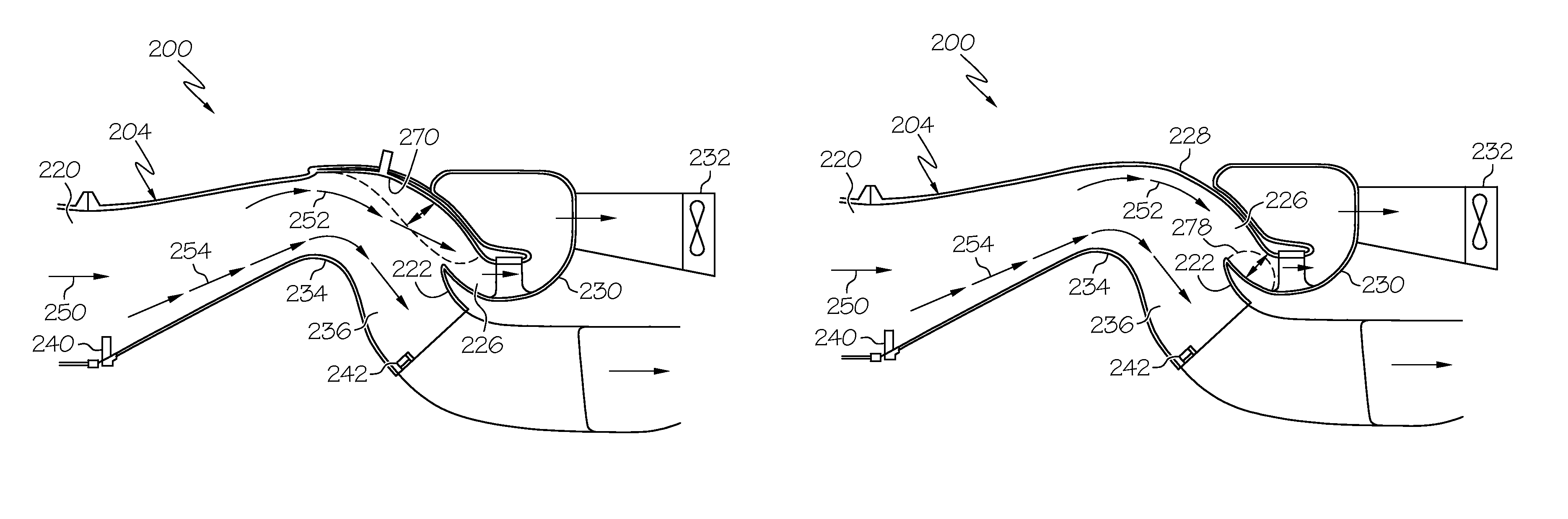
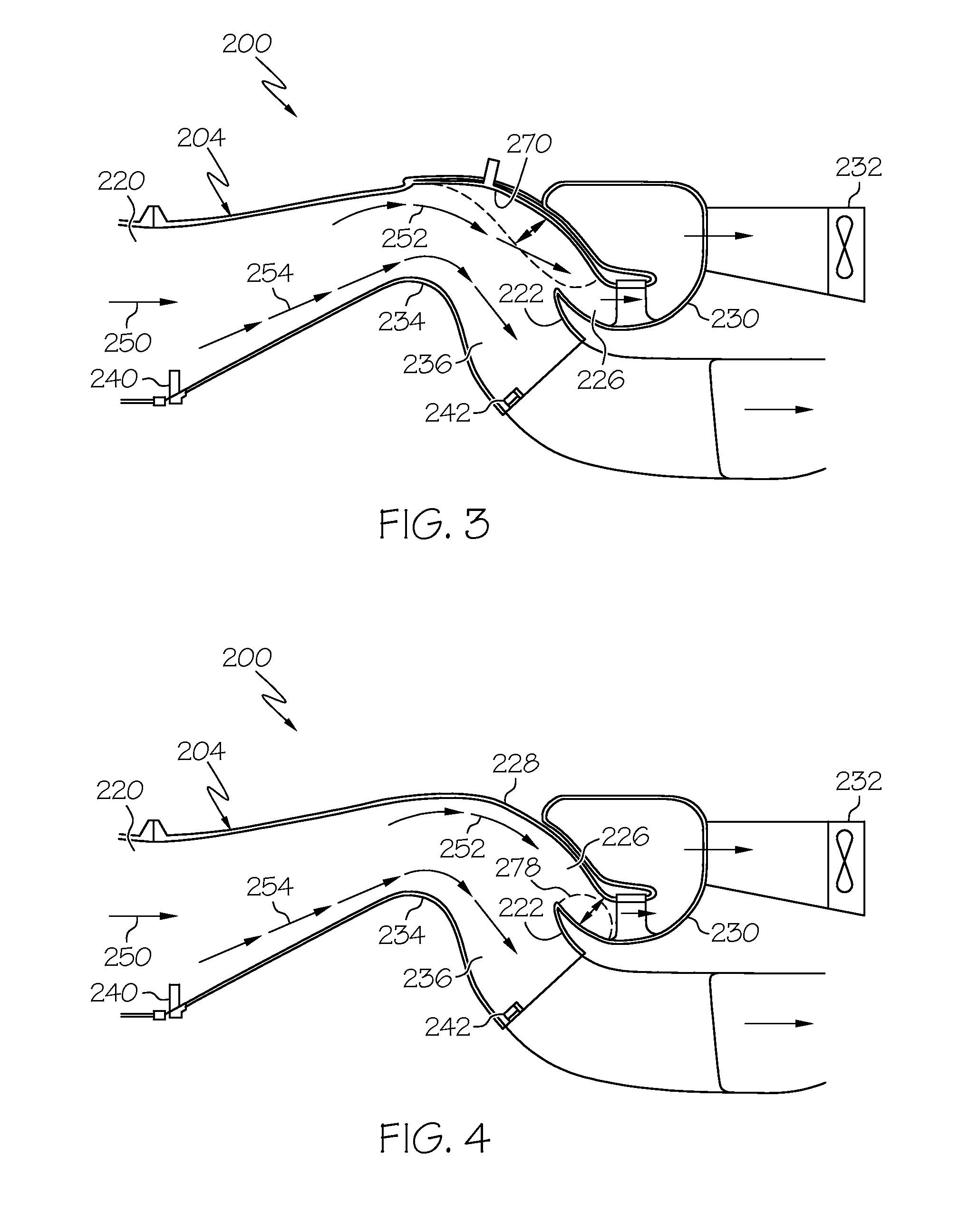
[0015]Embodiments described herein provide inertial inlet particle separator systems and method for separating particles from an inlet fluid and for providing the clean fluid to an engine. Particularly, the separator system and method enable the adjustment of the scavenge channel to adjust the geometry of the inertial inlet particle separator. Changing the geometry of the scavenge shroud or splitter can enable a smooth surface for air to be directed into the engine and / or optimize the ability to direct particles into the scavenge channel.

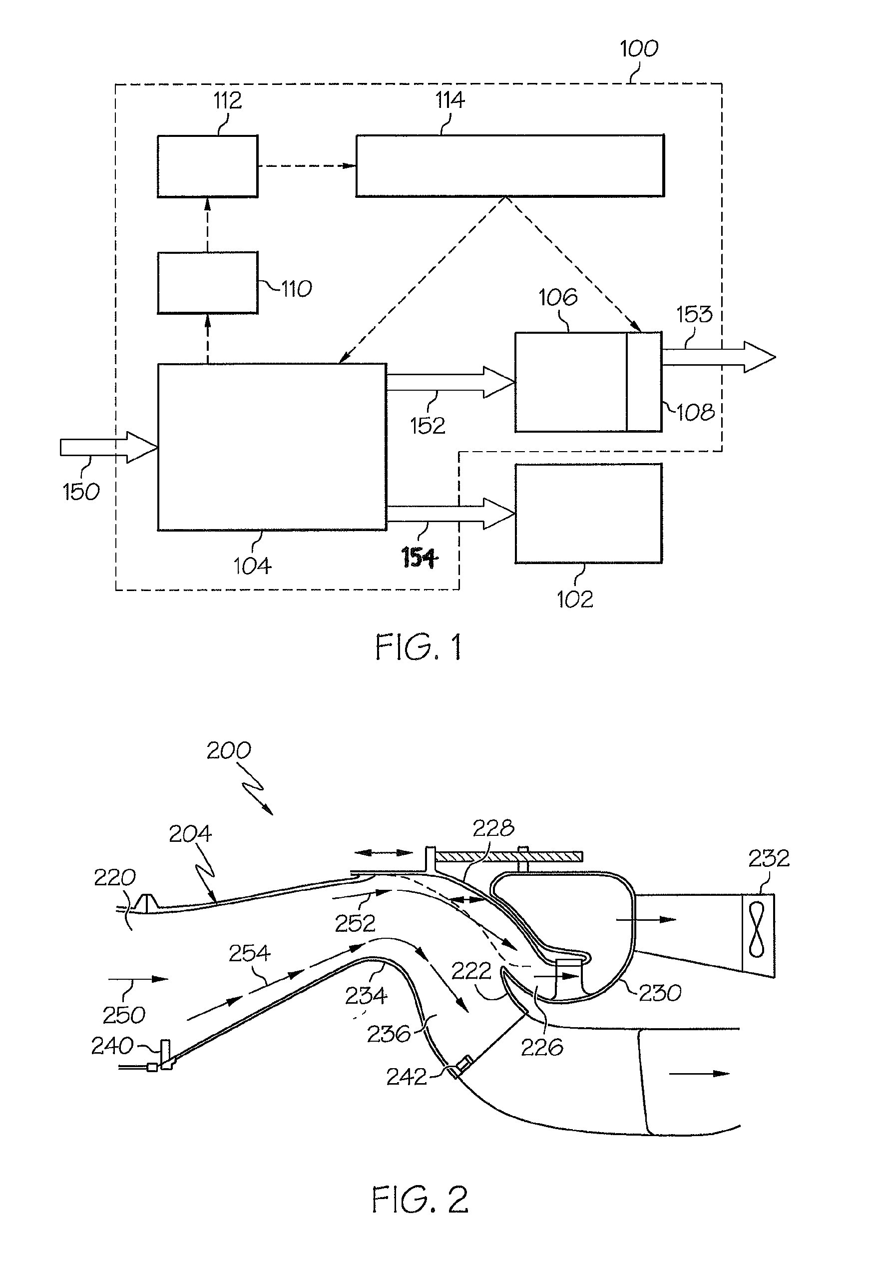
[0016]FIG. 1 is an exemplary block diagram of an inertial inlet particle separator system 100 coupled to an engine 102. The engine 102 can be, for example, ...


PUM

PropertyMeasurementUnit
sizeaaaaaaaaaa
speedaaaaaaaaaa
energyaaaaaaaaaa

Abstract

An inertial inlet particle separator system for a vehicle engine includes an inertial inlet particle separator and an adjustment mechanism. The separator includes a fluid inlet coupled to a scavenge channel and to a clean channel such that a first amount of fluid passing through the fluid inlet enters the scavenge channel and a second amount of fluid passing through the fluid inlet enters the clean channel. The scavenge channel is defined by a first wall and a splitter, and the clean channel is defined by a second wall and the splitter. The splitter and the second wall are stationary with respect to each other. The adjustment mechanism is coupled to the inertial inlet particle separator and configured to adjust a size of the scavenge channel. Although not necessarily, the adjustment mechanism may also be coupled to the scavenge fan speed.

Description

TECHNICAL FIELD[0001]The present invention generally relates to a fluid inlet for a vehicle engine, and more particularly relates to a method and system for separating particles from an inlet fluid within an aeronautical vehicle engine.BACKGROUND[0002]During operation of an aeronautical vehicle, fluids such as air are pulled into an engine and are used to generate energy to propel the vehicle. The fluids may contain undesirable particles, such as sand and dust, which can degrade engine components. In order to prevent this occurrence, at least a portion of the undesirable particles are separated from the fluids using an inertial inlet particle separator.[0003]A conventional inertial inlet particle separator typically includes a duct system with a fluid inlet that transitions into a scavenge channel that forms an in-line fluid path with the fluid inlet and a clean channel that branches off from the in-line fluid path. The inertia of particles in the fluid tend to make them travel in a...

Claims


Application Information

Patent Timeline
Patent Type & Authority Patents(United States)
IPC IPC(8): B01D45/00
CPCB01D45/04Y10S55/14
Inventor SHEORAN, YOGENDRA Y.JUDD, Z. DANIELANDERSON, MORRIS G.MURRAY, ROBERT S.
Owner HONEYWELL INT INC
Why Eureka
Try Eureka