Tie knot member

a tie knot and member technology, applied in the field of tie knot members, can solve the problems of not having immediate access to help, never becoming skilled at tying ties, and being extremely frustrating, and achieve the effect of eliminating frustration and avoiding embarrassmen

Inactive Publication Date: 2011-04-26
FUNK KELLY
View PDF38 Cites 8 Cited by
  • Summary
  • Abstract
  • Description
  • Claims
  • Application Information

AI Technical Summary

Benefits of technology

[0004]Accordingly, one object of the present invention is to eliminate the embarrassment of having to ask for help to tie a tie along with eliminating the frustration of having to re-tie the tie over and over again in attempts to get the perfect combination of length and knot as discussed above.

Problems solved by technology

One of the inherent issues with the traditional men's tie however is that unless a man learns to tie the tie correctly and do it on a regular basis, he never becomes skilled at tying ties.
This can become extremely frustrating.
Many persons also may not have immediate access to help at the time of fitting a tie so this may not even be an option.
For previously known devices such as the clip-on tie, people risked being humiliated by the possibility of a “clip-on” tie falling off and being ridiculed or laughed at for even wearing such a device.
Clip-on ties were never really accepted as being anything other than a cheap imitation of a tie that persons would wear simply because they did not have the skills necessary to tie a conventional neck tie.
Another inherent problem with such devices is that they were limited in available colors, designs, lengths and availability.

Method used


Image

  • Tie knot member
  • Tie knot member
  • Tie knot member

Examples


Embodiment Construction

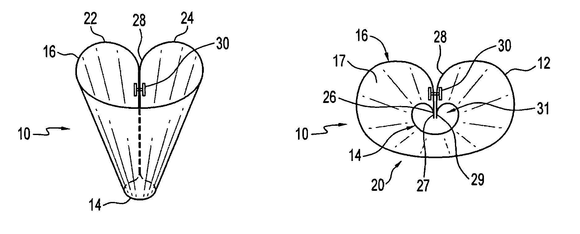
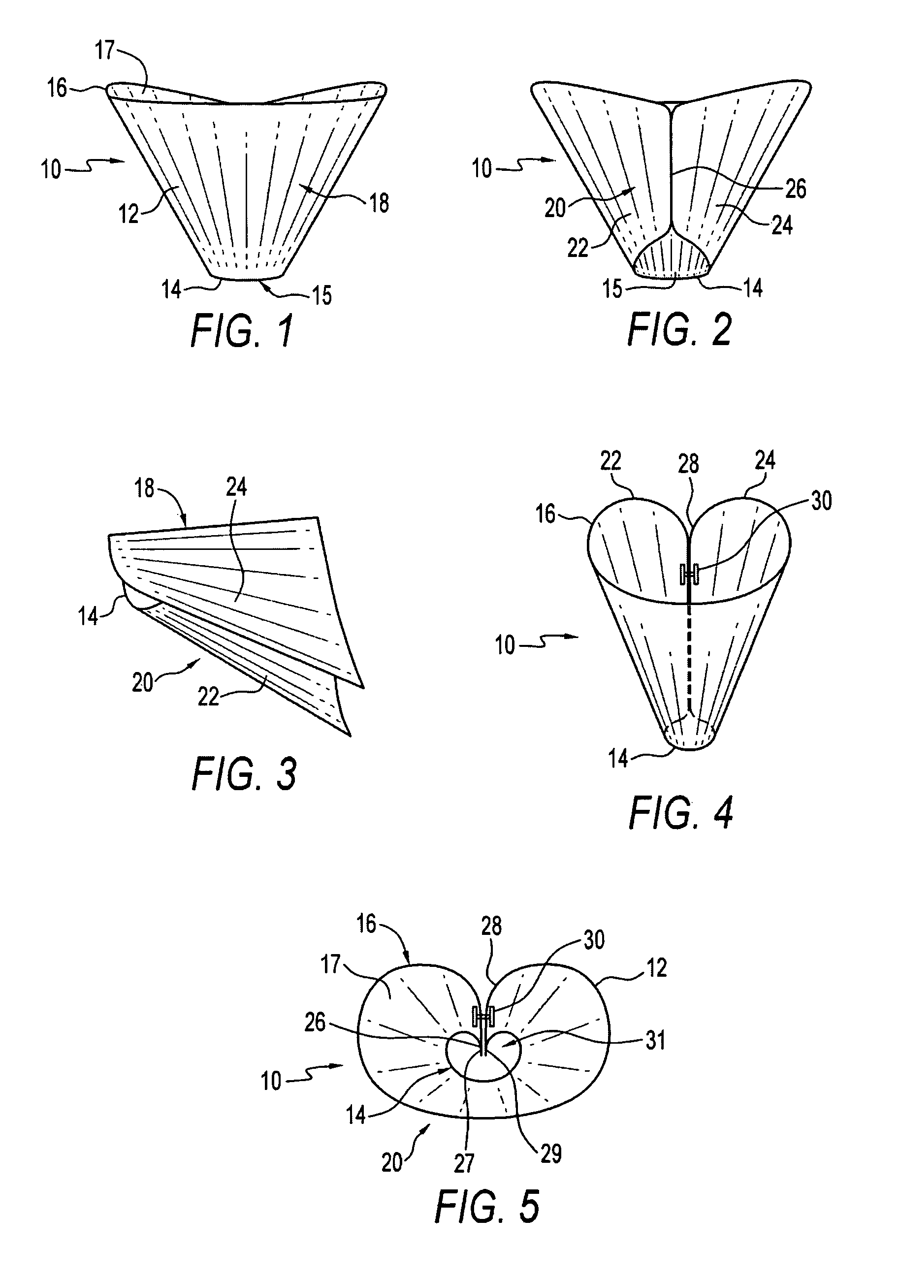
[0024]Referring to the drawings and first to FIG. 1, a tie knot member is illustrated as indicated by numeral 10. The tie knot member 10 also may be referred to as a cinching device. In this embodiment, the tie knot member 10 comprises a flexible member, in this case a shell 12 made of a flexible material. The shell 12 in this example is a resilient plastic although other materials could be used. The tie knot member 10 has a top end 16 with an upper aperture 17. The tie knot member has a base end 14 with a lower aperture 15. A front portion 18 extends between base end 14 and top end 16.

[0025]There is a rear portion 20 opposite the front portion 18, as illustrated in FIG. 2. The tie knot member 10 has cone members 22 and 24. Cone members 22 and 24 may be referred to as two truncated, partial cones, In this embodiment, the cone members abut adjacent to a slit 26. Each of the cone members is in the shape of a partial truncated cone, as best illustrated by FIGS. 3 and 4. The cone member...


PUM


Abstract

There is provided a tie knot member for an elongated strip of fabric. The tie knot member includes a shell having a truncated, conical shape with a cardioid-like cross-section. The shell has a base end with a lower aperture. The shell has a top end with an upper aperture. The shell has a rear portion extending between the base end and the top end. The rear portion includes a cusp and a pivotable connector connecting the shell across the cusp. The pivotal connector is so positioned to retain the shape of the shell, whereby when the elongated strip of fabric is passed through the shell and the shell is spread at the top end, the upper aperture is enlarged and the lower aperture is reduced, thereby cinching the lower aperture against the elongated strip of fabric.

Description

BACKGROUND OF THE INVENTION[0001]The traditional men's neck tie has been around for many years and has become the standard in most professional and business environments as part of the accepted dress code. One of the inherent issues with the traditional men's tie however is that unless a man learns to tie the tie correctly and do it on a regular basis, he never becomes skilled at tying ties. Some men therefore are either reluctant to wear a tie when it is called for or when it would be the appropriate dress-code for a particular environment.[0002]Any person who ever wore a tie can at some point and time remember getting dressed up for an occasion and attempting to tie a neck tie and then having to re-tie it many times over to get just the right knot and length. This can become extremely frustrating. The combination of getting a neck tie adjusted to the correct length with the correct knot is clearly something that takes practice and is an art that many average people do not master b...

Claims


Application Information

Patent Timeline
Patent Type & Authority Patents(United States)
IPC IPC(8): A41D25/00A41D25/02
CPCA41D25/022Y10T24/1986
Inventor FUNK, KELLY
Owner FUNK KELLY
Why Eureka
Try Eureka