
Distributed beacon enabled wireless networks

a wireless communication network and beacon technology, applied in the field of wireless communication network beacons, can solve the problems of large expenses if not detected, complex networks, high cost, etc., and achieve the effect of improving channel efficiency, reducing the risk of data traffic, and improving reliability

Active Publication Date: 2011-05-03
MITSUBISHI ELECTRIC RES LAB INC
View PDF6 Cites 21 Cited by
  • Summary
  • Abstract
  • Description
  • Claims
  • Application Information

AI Technical Summary

Benefits of technology

[0034]The network offers a very reliable communication services. It offers low latency by providing opportunities for retransmission of failed data frames in the same super frame. It offers a certain degree of determinism in the sense that data frame will be delivered in the same super frame. That is, the super frame duration defines maximum transmission delay for one hop transmission. The network is adaptive to burst traffic in the sense that the nodes having unusual data arrivals can request for additional bandwidth from a coordinator node. This bandwidth is dynamically allocated in the same super frame. The protocol does not require assistance from higher layers in the network protocol stack for channel access management.

Problems solved by technology

A machine failure can cause large expenses if not detected, when compared to the cost of a systematic shut down of a machine for service well before the machine fails.
However, scalability, reliability, and latency are challenging issues.
Such networks, however, are costly, complex, and inflexible.
That can not be cost effective, and can force a prolonged down time.
The challenge, however, lies in providing a similar degree of reliability and latency as offered by their wired networks.
Limited resources that are generally available to sensor nodes effectively preclude the use of forward error correction codes or other computationally intensive approaches.
However, the current IEEE 802.15.4-2006 standard fails to satisfy the stringent requirements for latency and reliability performance necessary for industrial deployments.
The central management approach is generally not very feasible and scalable for large multi-hop wireless sensor networks, where the channel condition can change frequently, routes can not be reliable, and the network topology can not be available.
In such networks, managing network resources efficiently and keeping a central repository of resources' allocation updated is not a simple or feasible task.
More important, TDMA based systems lack the required flexibility to handle failed transmissions, which are common in wireless sensor networks, because of their inability to provide opportunities for retransmission.
Moreover, because the time slots are generally allocated in a static non-adaptive manner, those systems are normally ill prepared to handle burst traffic.
That can result in two undesirable factors.
First, the network becomes inefficient.
The latency in responding to changes in a volatile operating environment, which wireless sensor networks normally operate in, makes the network less adaptive.
Secondly, it makes the design of higher layers, including the application network designs, more difficult because of limited familiarity with the issues and problem related to the lower level network components.
However, throughput is degraded due to collisions between transmissions.
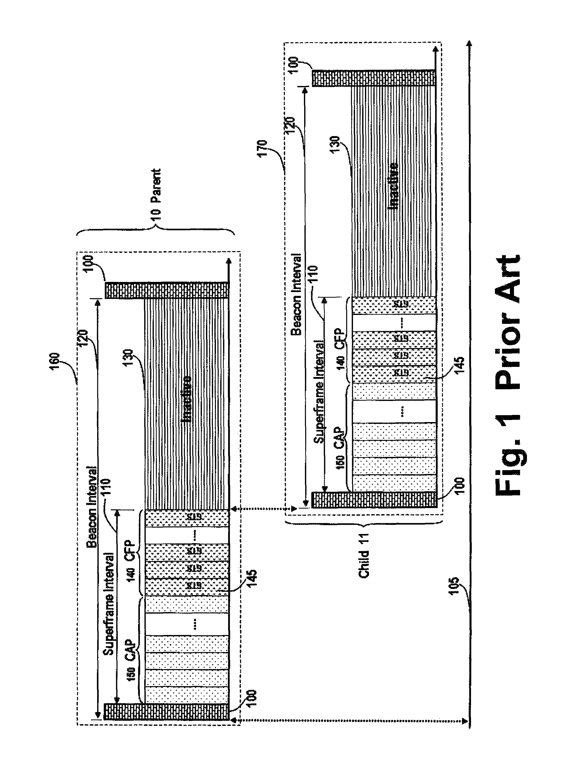
However, the IEEE802.15.4-2006 standard fails to satisfy the performance requirements for industrial deployments, including scalability, reliability, and latency issues.

Method used


Image

  • Distributed beacon enabled wireless networks
  • Distributed beacon enabled wireless networks
  • Distributed beacon enabled wireless networks

Examples


Embodiment Construction

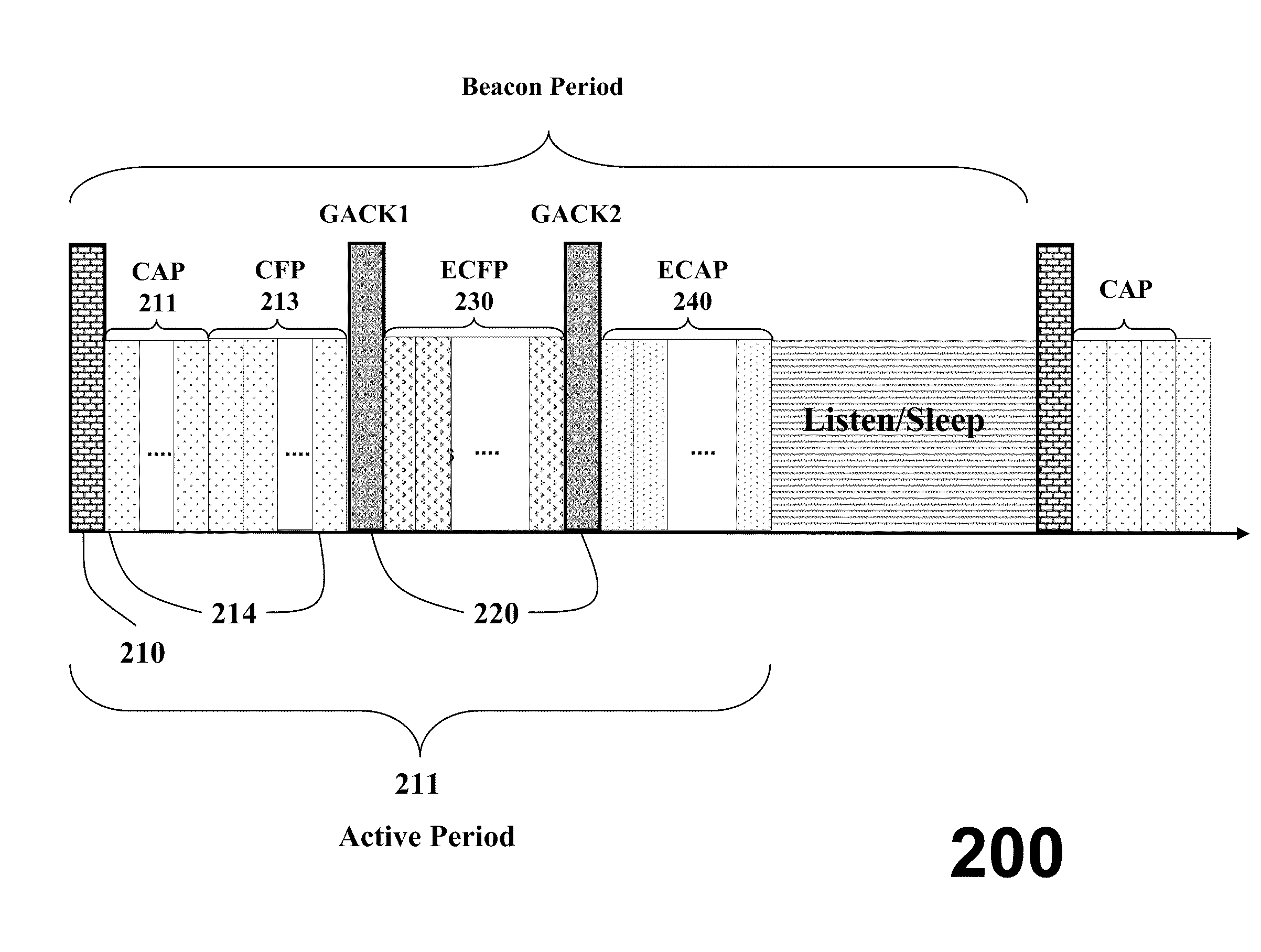
[0033]The embodiments of our invention provide a protocol that operates in a distributed manner in a network of transceiver nodes, and offers an automatic resource management mechanism that is distributed in its nature, and scalable. The protocol uses period announcement cycles to specify a communication schedule for the nodes.

[0034]The network offers a very reliable communication services. It offers low latency by providing opportunities for retransmission of failed data frames in the same super frame. It offers a certain degree of determinism in the sense that data frame will be delivered in the same super frame. That is, the super frame duration defines maximum transmission delay for one hop transmission. The network is adaptive to burst traffic in the sense that the nodes having unusual data arrivals can request for additional bandwidth from a coordinator node. This bandwidth is dynamically allocated in the same super frame. The protocol does not require assistance from higher l...


PUM


Abstract

In a wireless network that includes multiple nodes, each periodic announcement cycle of a communication schedule is partitioned into a set of time slots, including a set of management time slots, a set of beacon time slots, and a set of superframe time slots. Management frames are broadcast during the management slot to specify beacons. Beacons are transmitted during the beacon slots to specify when to transmit the superframes during the superframe time slots.

Description

RELATED APPLICATIONS[0001]This Non-Provisional Application claims priority to U.S. Provisional Application 61 / 078,616, “Distributed Beacon Enabled Wireless Networks,” filed by Bhatti et al. on Jul. 7, 2008; and 61 / 037,395, “Hybrid Multiple Access Method and System in Wireless Networks with Extended Content Free Access Period,” filed by Sahinoglu et al. on Mar. 18, 2008 incorporated herein by reference.FIELD OF THE INVENTION[0002]This invention relates generally beacon signals in wireless communication networks, and more particularly to networks designed according to the IEEE 802.15.4-2006 standard.BACKGROUND OF THE INVENTION[0003]Wireless sensor networks (WSN) are deployed in many industrial and commercial environments. Applications in industrial environments offer an enormous business potential for these types of networks. A machine failure can cause large expenses if not detected, when compared to the cost of a systematic shut down of a machine for service well before the machine ...

Claims


Application Information

Patent Timeline
Patent Type & Authority Patents(United States)
IPC IPC(8): H04J3/08H04B7/212
CPCH04W28/06H04W28/04H04W84/18H04W72/04H04W48/08
Inventor BHATTI, GHULAMSAHINOGLU, ZAFER
Owner MITSUBISHI ELECTRIC RES LAB INC
Learn More